LONWORKS BUS I/O MODULES – PRODUCT DATA
EN0Z-0980GE51 R0119
14
Relay Output Modules
1
3
2
5
4
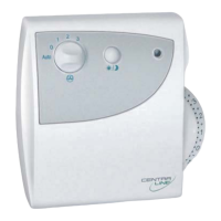
Fig. 19. CLIOLR824A L
ONWORKS Bus Relay Output
Module (shown with terminal socket)
Legend
1 LONWORKS service button S1
2 Manual overrides
3 Status LEDs
4 Service LED
5 Power LED
The CentraLine L
ONWORKS Bus Relay Output Modules, with 6
relay outputs, are available in the following versions:
CLIOP824A L
ONWORKS Bus Relay Output Module
(without manual overrides)
CLIOPR824A L
ONWORKS Bus Relay Output Module (with
manual overrides)
They are installed with the XS824-25 or XSU824-25 Terminal
Socket.
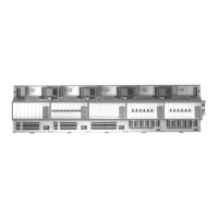
REMOVABLE CROSS CONNECTOR (FACTORY-MOUNTED)
NO
NC
COM
11
12
13
NO
NC
COM
21
22
23
31
32
33
NO
NC
COM
41
42
43
NO
NC
COM
51
52
53
NO
NC
COM
61
62
63
NO
NC
COM
25
71
75
72 76
73 77
74
78
COM
A
COM
A
COM
B
COM
B
24
V~
24
V~
24
V~0
24
~0
RELAY BLOCK 1 RELAY BLOCK 2
Fig. 20. CentraLine L
ONWORKS Bus Relay Output Modules
(schematic)
Features
- Cross-Connecter
- 1 yellow LED per output
- Optional versions with manual override switches (Auto, 0,
1; LED flashes in override mode)
- Feedback on manual override signal
- Configurable safety position for outputs in case of
communications problems (remain, OFF, ON)
- Permissible load per Relay Output Module (total)
Max. load (fuse F3):
19…250 VAC: 12 A
1…29 VDC: 12 A resistive, 3 A inductive
- Permissible load per normally-open contact:
Max. load:
19…250 VAC: 4 A resistive or inductive
1…29 VDC: 4 A resistive, 1 A inductive
Min. load: P > 50 mW
- Permissible load per normally-closed contact:
Max. load:
19…250 VAC: 2 A resistive, 1 A inductive
1…29 VDC: 4 A resistive, 1 A inductive
Min. load: P > 50 mW
 Loading...