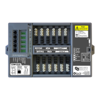
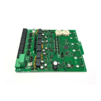
LONWORKS BUS I/O MODULES – PRODUCT DATA
EN0Z-0980GE51 R0119
3
Table 3. Pluggable LonWorks Bus I/O Module specifications
Module
Analog Input Analog Output Binary Input Relay Output
CLIOL821A CLIOL822A, CLIOLR822A CLIOL823A CLIOL824A, CLIOLR824A
no. of I/Os 8 analog inputs 8 analog outputs 12 binary inputs
requiring a gold contact
or open collector
6 relay outputs
characteristics Linear Graph, 0...10 VDC with pull-
up, 0(2)…10 VDC without pull-up
NTC20kΩ (-50…+150 °C, default)
NTC10kΩ (-30…+100 °C)
PT
1000-1
(-50…150 °C)
PT
1000-2
(0…400 °C)
Johnson A99 PTC (-40…+120 °C)
NI1000TK5000 (-30…+130 °C)
PT
3000
(-50…150 °C)
BALCO
500
(-30…120 °C)
Also configurable as:
binary inputs
Linear graph (0…10 V with pull-up)
Features:
16-bit resolution
configurable offset per input
auxiliary voltage: 10 VDC, I
max
=
5 mA
0…11 VDC / 1 mA
Also configurable as: floating
outputs or binary outputs (0 V
/ 10 V)
Features:
8-bit resolution (default)
Safety position (remain, 0%,
50%, 100%)
red LED per output
light intensity follows output
level in auto
Version with manual
override (R):
1 potentiometer per output
auto feedback signal (mode
+ value)
blinking in manual override
position
static binary input,
(default: dry contact)
Also configurable as:
totalizers (20 Hz)
Features:
1 LED per input
Color mode can be
set per input to
OFF/yellow or
green/red using
CARE / COACH AX /
COACH NX
ON: < 1.6 kΩ to GND
or < 2.5 V to GND,
OFF: > 90 kΩ to
GND or > 4 V to
GND
relay outputs (default)
Features:
Changeover relays
Voltage: 19…250 VAC,
1…29 VDC, P>50 mW
max. total current: 12 A
current per relay: N.O.: 4(4) A
(AC) or 4(1) A (DC),
N.C.: 2(1) A (AC) or 4(1) A
(DC)
Safety position (remain, 0%,
100%)
yellow LED per output
Version with manual override
(R):
1 switch per output
auto feedback signal (mode +
value)
blinking in manual override
position
Manual Overrides as per EN ISO 16484-2:2004
The manual override switches and potentiometers of the output modules support direct operation as per EN ISO 16484-
2:2004, section 5.4.3 "Local Priority Override/Indicating Units."
Specifically, the positions of the manual override switches and potentiometers directly control the outputs – independently
of the controller and HMI. When a manual override switch or potentiometer is not in its default position ("auto"), the
corresponding output LED will blink continuously, and the output module will send a feedback signal with the status
"manual override" and the given override position to the controller (which will then also store this information in its alarm
memory).
NOTE: When updating the firmware of output modules, their outputs are turned OFF – regardless of the position of their
manual override switches and/or potentiometers.
 Loading...


