EasyManua.ls Logo

Honeywell D User Manual

Honeywell D
8 pages
To Next Page IconTo Next Page
Page #1 background imageLoading...
Page #1 background image
X-XX UL
INSTALLATION INSTRUCTIONS
®U.S. Registered Trademark
Copyright © 1998 Honeywell Inc. • • All Rights Reserved
T8112C,D Electronic
Programmable Thermostats
APPLICATION
The T8112C,D thermostats provide electronic
programmable control for 24 to 30 Vac heating and
cooling systems.
RECYCLING NOTICE
If this control is replacing a control that contains
mercury in a sealed tube, do
not
place your old
control in the trash.
Contact your local waste management authority
for instructions regarding recycling and the proper
disposal of the old thermostat.
INSTALLATION
When Installing this Product…
1. Read these instructions carefully. Failure to follow
them could cause a hazardous condition.
2. Check the ratings given in the instructions and on
the product to make sure the product is suitable for
your application.
3. Installer must be a trained experienced service
technician.
4. After installation is complete, check out product
operation as provided in these instructions.
CAUTION
1. Disconnect power supply to prevent electrical
shock or equipment damage.
2. After wiring is complete, push excess wire
back into the hole and plug hole with
nonhardening caulk, putty or insulation to
prevent drafts from affecting thermostat
operation.
Location
Install the thermostat about 5 ft. (1.5m) above the floor in
an area with good air circulation at average temperature.
Do not install the thermostat where it can be affected by:
drafts, or dead spots behind doors and in corners.
hot or cold air from ducts.
radiant heat from sun or appliances.
concealed pipes and chimneys.
unheated (uncooled) areas such as an outside wall
behind the thermostat.
Mounting Plate Installation
Position mounting plate on the wall. Use a level to make
sure mounting plate is level. Use a pencil to mark the two
mounting holes. See Fig. 1.
WALL
WIRES THROUGH
WALL OPENING
WALL ANCHORS (2)
MOUNTING
PLATE
MOUNTING
SCREWS (2)
M1718
69-0917-2
Fig. 1. Mounting plate installation.
Question and Answer IconNeed help?

Do you have a question about the Honeywell D and is the answer not in the manual?

Honeywell D Specifications

General IconGeneral
Power SourceBattery
Display TypeDigital
Backlit DisplayYes
Hold FeatureYes
Filter Change AlertYes
Temperature Range40°F to 90°F

Summary

APPLICATION

RECYCLING NOTICE

Important notice regarding recycling of old thermostats containing mercury.

INSTALLATION

When Installing this Product...

Read instructions, check ratings, ensure qualified installer, and test operation.

CAUTION

Disconnect power before electrical work and seal wire holes to prevent drafts.

Location

Install thermostat 5 ft. above floor in area with good air circulation, avoiding drafts and heat sources.

Mounting Plate Installation

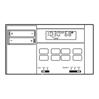
Position mounting plate, use level, mark holes, and install anchors.

Adjust Fan Operation Switch, as Required

Set FUEL SWITCH to F for most systems; E for electric heat systems.

Adjust System On-time, as Required

Adjust screws A and B for different heating systems to optimize on-time and minimize swings.

Wiring Thermostat

Connect system wires to thermostat terminals according to local codes and diagrams.

CAUTION

Disconnect power before wiring to prevent electrical shock or equipment damage.

Mounting Thermostat on Mounting Plate

Engage top tabs and press lower edge of thermostat case to latch onto mounting plate.

Installing Batteries

IMPORTANT

Batteries are essential for programming and operation; use alkaline AA batteries.

SETTINGS

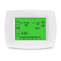
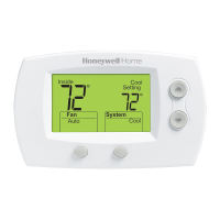
Covers setting current time/day, fan switch, and system switch.

Current Time/Day

Instructions to set the current time and day using the Set Clock/Day and Time keys.

Fan Switch

Explanation of FAN AUTO and FAN ON modes for fan operation.

System Switch

Describes the function of the System switch positions: COOL, OFF, and HEAT.

CHECKOUT

Heating

Instructions for checking heating system operation by jumpering R and R wires at the thermostat.

Cooling

Advice to avoid compressor damage by not operating cooling below 50°F and noting a potential 5-minute delay.

Fan

Steps to test fan operation using system and fan switches, including checking fan behavior with HEAT and COOL settings.

TROUBLESHOOTING GUIDE

If...

Lists common issues like no display, incorrect temperature range, or timing errors, with corresponding solutions.

NOTICE

States compliance with Canadian Radio Interference Regulations as a Class B digital apparatus.

Related product manuals