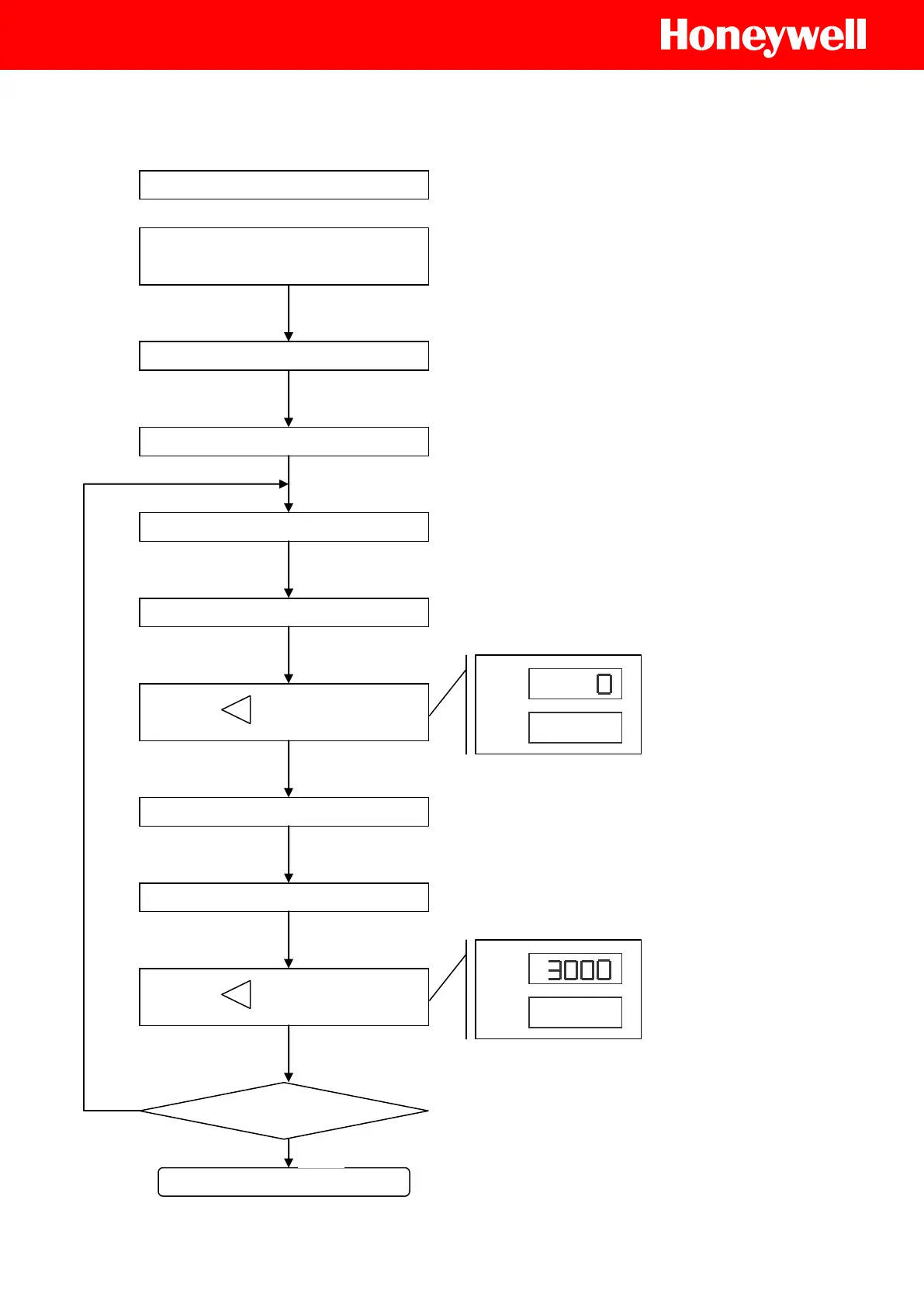
4-4. Procedure of Calibration
(Range of PV : 0~3000, Input : 4~20mA)
‘SET 2.2 = 1’
(To activate the steps of ANL1 &
ANH1 )
Set INP1(Level 3), 4~20mA : AN5
(Refer to ‘3. Linear Input H/W
Setting’)
Define LSPL & USPL in Level 3
Assuming LSPL = 0, USPL = 3000
Input ‘Lower Limit signal’
In case of 4~20mA, input 4mA
DP : Decimal Point
Set Decimal point place
Go to ‘ANL1’ step in Level 3
Press ‘ ’ key, adjust ‘ANL1’
Adjust SP, until ‘PV=LSPL’
(In case of this, PV=0)
Press ‘ ’ key, adjust ‘ANH1’
Go to ‘ANH1’ step in Level 3
Input ‘Upper Limit signal’
In case of 4~20mA, input 20mA
Adjust SP, until ‘PV=USPL’
(In case of this, PV=3000)
Check LSPL, USPL if right value
(Input Lower/Upper Limit signal, Check)
In case of Linear input model,
The default is ‘SET2.2 = 1’
 Loading...


