8
INSTALLATION (CONT)
With Searchline Excel Cross-Duct
The DVC100 (M) is tted to the Cross-Duct mounting plate and then the units
are wired.
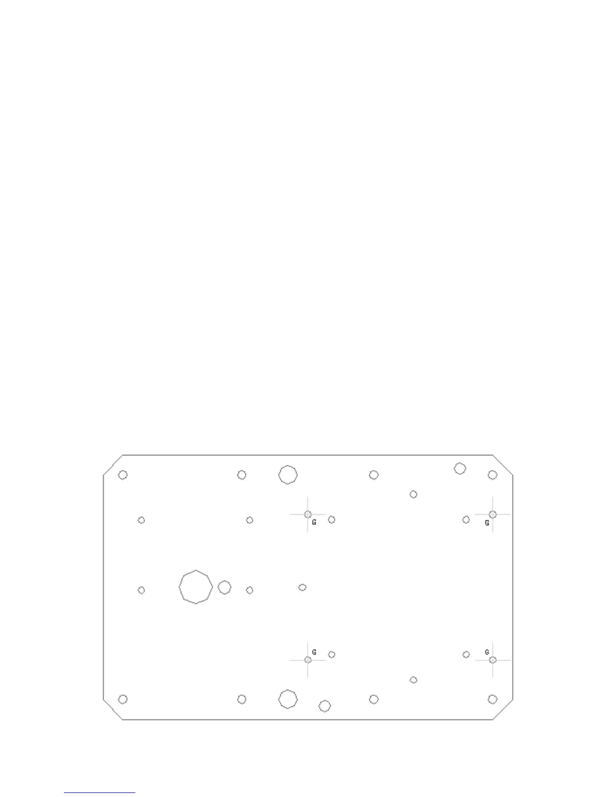
(1) Securely t the Termination Unit to the mounting plate so that the
communications link entry socket connector is located at the bottom.
Use the mounting holes marked G on the diagram below.
(2) Remove the Termination Unit lid.
(3) Attach the two cables from the Searchline Excel Cross-Duct gas detector
to the Termination Unit.
Fit the transmitter's cable to the bottom left entry after removing the 3/4 NPT
blanking plug. Fit the receiver's cable to the right-hand entry (see diagram).
Use suitably approved certified glands/adaptors.
(4) Fit an approved certied cable gland to the Termination Unit cable entry
as necessary.
(5) Fit the external eld wiring through the cable gland tting and secure.
(6) Terminate the gas detector and eld wiring.
Refer to Electrical Installation.
 Loading...