E528 Product Guide
Rev 8.0 12/16/2016 10
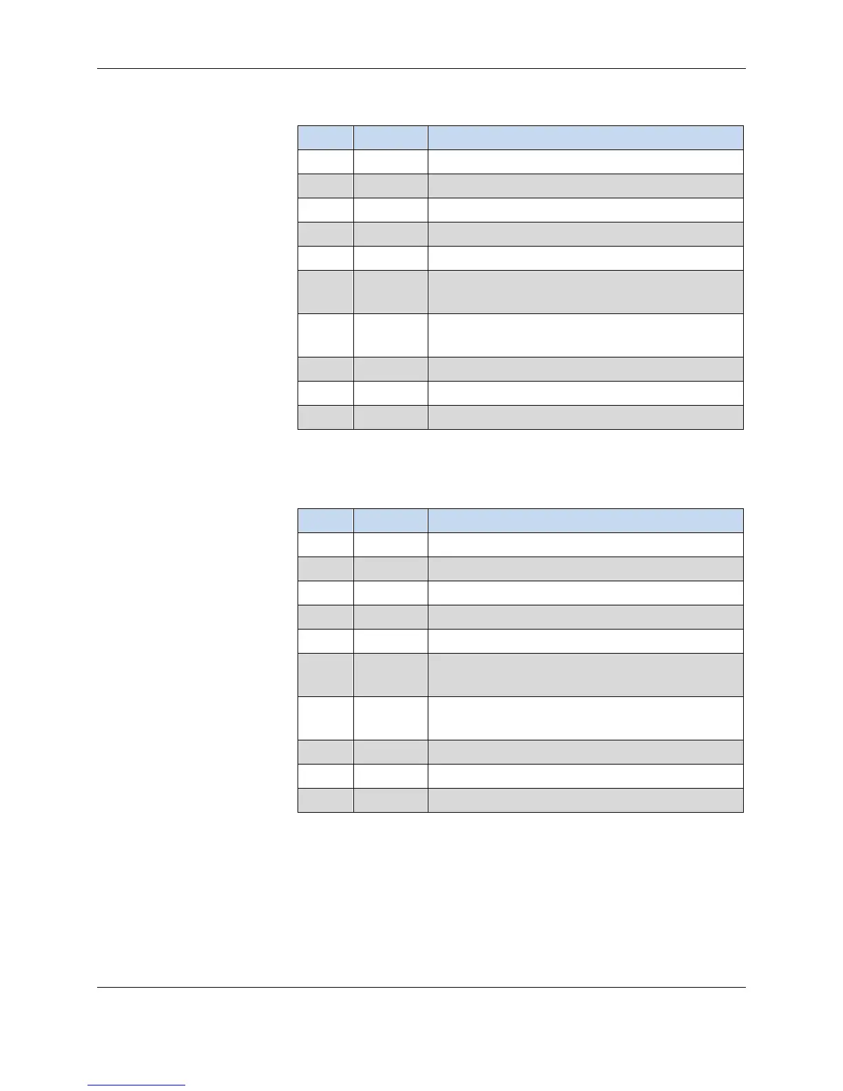
Pin Color Typical Function
1 Green Ground
2 Red 24VAC
4 Blue High Fan
Medium Fan or Second Stage Heat
6 Yellow Cold Water Valve (FCU) or Compressor Signal
(Heat Pump)
7 White Hot Water Valve (FCU) or Reversing Valve
(Heat Pump)
8 Grey Valve Power
9 Violet Fan Power
10 Orange Low Fan
Pin Color Typical Function
2 Black Line
4 Yellow High Fan
5 Orange Medium Fan or Second Stage Heat
6 Red Cold Water Valve (FCU) or Compressor Signal
(Heat Pump)
Hot Water Valve (FCU) or Reversing Valve
(Heat Pump)
8 Grey Valve Power
10 Blue Low Fan
Wiring
The steps below provide an overview of the wiring process. Refer to the as-
built wiring diagrams provided for exact details.
1. If applicable, use wire nuts to connect the 6-pin low-voltage harness wires
to the applicable low-voltage communication (if e528 is part of a wired
Table 4. 24VAC Harness Color Code, Pinout, and Typical Functions
24VAC Harness
Table 5. 100-277VAC Harness Color Code, Pinout,
and Typical Functions
100-277VAC Harness
 Loading...