E528 Product Guide
Rev 8.0 12/16/2016 12
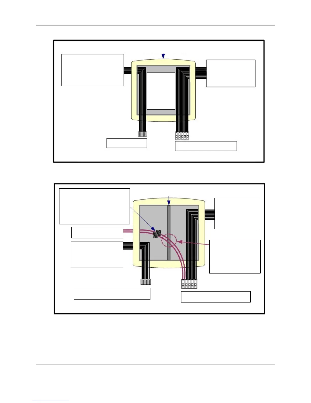
Figure 10 Electrical Box Connections Line and Low Voltage
communication
door/window switch,
external PIR wiring
power, valve/fan
control from HVAC
equipment
To E528 10-pin Molex Socket
connections
should follow
the National
Electric Code
and adhere to
all local
Figure 11. Electrical Box Connections 24VAC
24-volt and ground wires must
be routed to the low voltage side
of the box, passing over the top
of the physical separator. They
should be connected on the low-
voltage side with appropriate
communication
door/window switch,
VAC power
valve/fan control
wiring from HVAC
equipment
wires (shown in plum
for emphasis) MUST
PASS OVER the
physical separator to
the low voltage side
To E528 low voltage comm header
To the E528 10-pin Molex Socket
 Loading...