DOCUMENT: FC1: MARKINGS AND DEVICE SEALING
PAGE: 11 OF 12
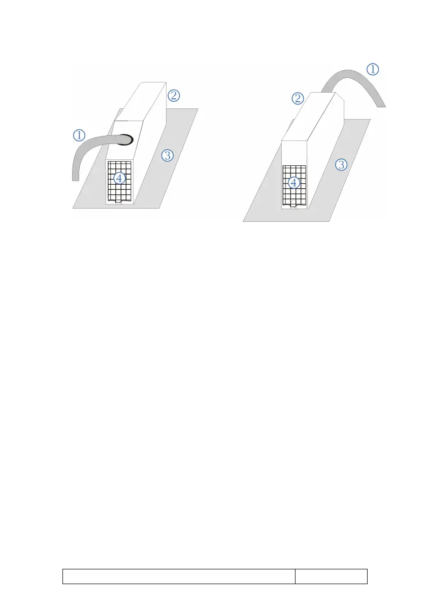
Figure 11 (schematic): Sealing of ExMFE5 plug-in connectors with adhesive
labels (view from below and from above, cable feeding from below or from
above, depending on installation situation)
Sensor and transmitter lines
Connector housing
Rear panel
Securing mark (adhesive labels)
Sealing of MFE7 connectors
In case of an MFE7 board, there are two connectors for connecting all
available lines: One connector for two current/HART interfaces and one
resistance input, the second one for three pulse or signal inputs and a serial
RS485 interface. There are also two alternatives for securing these
connectors. The standard method is to secure the drilled screws fixing the
connector with a wire and a seal as shown in Figure 10
.
If required (depending on the installation situation), the MFE7 screw
connections can alternatively be secured by using securing marks in form of
adhesive labels. One securing mark per connector is sufficient (to secure the
upper OR the lower screw connection, cf. Figure 11) as these connectors
are shorter compared to the ExMFE5 connectors.
 Loading...


