www.honeywellvideo.com
+1.800.796.CCTV (North America only)
HVSsupport@honeywell.com
© 2008 Honeywell International Inc. All rights reserved. No part of this publication may be reproduced by any means without written permission from Honeywell Video
Systems. The information in this publication is believed to be accurate in all respects. However, Honeywell Video Systems cannot assume responsibility for any
consequences resulting from the use thereof. The information contained herein is subject to change without notice. Revisions or new editions to this publication may
be issued to incorporate such changes.
Document 800-01741 – Rev B – 08/08
Audio and Alarms
Connect a twisted pair (UTP) cable from each peripheral alarm contact
to each alarm input on the terminal block. Configure as normally open
(NO) or normally closed (NC). For detailed audio and alarm
connection information, see the EQUIP™ Series Fixed Mini Dome
Network Camera Reference Guide located on your CD.
Note For secure installations, protect surface mounted cables
with plastic or metal cable covers.
Adjust the Field of View
1. Apply power to the camera.
2. Connect the service monitor cable to the video monitor output
and monitor the video signal.
3. Loosen the setscrew that locks the gimbal assembly in place to
adjust the horizontal rotation (see illustration below).
4. Adjust the camera to the desired view. Orient as shown below to
maintain the correct picture orientation.
5. Retighten the locking screw to lock the gimbal assembly in
place.
6. Disconnect the service monitor cable.
Install the Enclosure Cover
Network Setup
Honeywell IP Utility
Note Before installing and using the Honeywell IP Utility, make
sure that your camera is connected to your network
through a CAT5 Ethernet cable.
To discover the HD4DIP devices and configure their network settings,
you must first install the IP Utility. See the Reference Guide on your CD
for system requirements. You must have Windows administrator
privileges for the workstation on which the Honeywell IP Utility is being
installed.
1. Insert the CD. Autorun will start the installation. If autorun does
not start, browse to the CD drive and run Honeywell IP Utility
Setup.exe.
2. Follow the steps in the InstallShield Wizard.
3. Log on to the IP Utility:
a. Double-click the IP Utility icon ( ) on the desktop. The
logon dialog box appears.
b. From the Username list, select Administrator or Guest.
c. Type the case-sensitive Password and click . The
default passwords are 1234 (Administrator) or guest
(Guest user).
Configuring the Network
1. After you log on, the devices on the network are automatically
discovered and listed in the Discovery pane. After the initial
discovery, auto-refresh continues to discover newly added or
removed network devices.
2. Connect to your HD4DIP device by double-clicking it in the
Discovery pane or by selecting it and clicking .
3. Configure the IP network settings:
• Automatically. Connect to the device, click the System
tab, select to Obtain an IP Address automatically and
click Apply. The network settings are assigned from the
network server automatically. Enter the Device Name.
• Manually. Connect to the device, click the System tab.
Make sure Obtain an IP Address automatically is not
selected then enter the Device Name, IP Address, Subnet
Mask, Default Gateway and MAC Address. Click Apply.
Caution Check the values for the IP network settings before
submitting. Incorrect values might cause a failure when
connecting the tool to the device.
Note Contact your network administrator if you have any network
related issues or questions about your network.
Operate Your Camera
The camera has a Web-Client that enables you to view video and
configure device settings for the camera using a standard web
browser. See the EQUIP Series Fixed Mini Dome Network Camera
Reference Guide to set up your web browser to view video. To log on
to the Web-Client application:
1. Launch Internet Explorer and enter the URL (IP address) for the
network camera.
OR, launch the Web-Client application from the IP Utility by
clicking Launch Browser.
2. Select the User Name as Administrator or Guest.
3. Enter the case-sensitive password and click . The default
passwords are 1234 (Administrator) or guest (Guest user).
In Out
Audio
Alarm
In Out
PIN Definition
1 Audio In +
2 Audio In –
3 Audio Out +
4 Audio Out –
5Alarm In +
6Alarm In –
7Alarm Out +
8Alarm Out –
Legend
A = Tilt rotation
B = Horizontal rotation
C = Pan rotation
Angle view
Top view
B
C
A
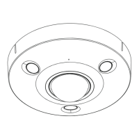
Setscrew (loosen
to adjust horizontal
rotation)
Loosen locking screw (inside
conduit entry) to remove the
side conduit plug.
Set focus (top)
Set focal length
(bottom)
HD4DIP dome enclosure
Use Allen key (supplied) to
secure dome enclosure to base
with four #8-32 security screws
 Loading...