DISTRIBUTED I/O – PRODUCT DATA
EN0B-0090GE51 R0316 12
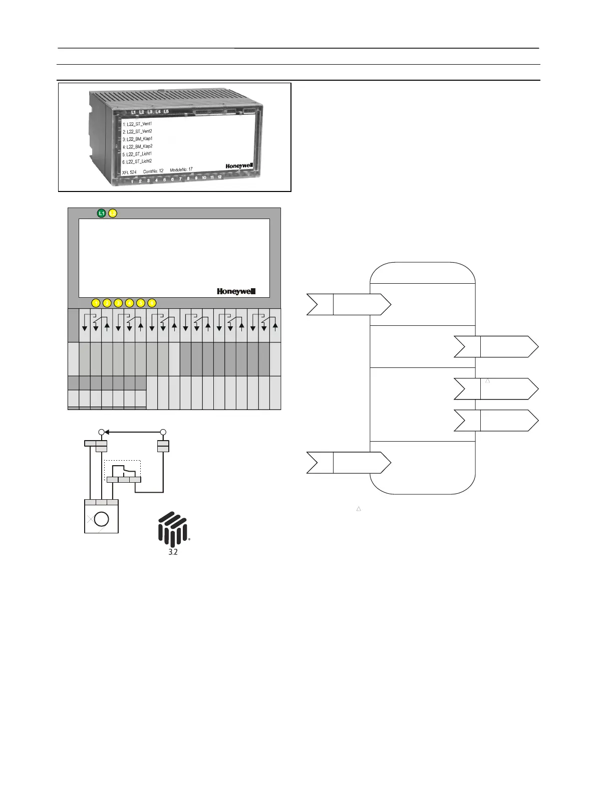
Digital Output Module XFL524B
Six isolated change-over contacts
Max. voltage U
max
= 230 Vac per output
Max. current I
max
= 2 A per output
LED per channel
OFF: LED off
ON: LED illuminated (yellow)
Green power LED (L1) and red L
ONWORKS status LED (L2)
Cycle time 1 sec with CPU
Dimensions (WxLxH): 47x97x70 mm
XFL524B
2
1
29
28
26
25
24
23
22
21
20
19
A1
A2
30
31
32
33
34
D
D
27
blue
br.
41
40
39
38
37
36
35PE
gr/ye
13
14
15
16
17
18
3
4
5
6
7
8
9
10
11
12
K1 K2 K3 K4 K5 K6
L1N
35 27
28 20
19
1 2 3
~230 V
PE 0
230 V
M
Fig. 14. XFL524B terminals / wiring examples
The digital output module has six isolated change-over con-
tacts which can be connected to actuators or other switchable
devices.
The unit plugs into the XSL514 Terminal Block and can be
inserted and removed without disturbing other units on the
bus. Terminals 1 through 18 are switched according to Fig.
14. Six LEDs are located on top of the module. The module
address is set using the rotary HEX switch (in the case of
applications prior to CARE 4.0).
Beginning with Excel 500 controller firmware version 2.04.00,
the online point attribute Normally Open / Normally Closed
(NO/NC) defines the relation between the physical state (relay
on/off) and its logical status. See Table 11.
Open Loop Actuator
Object Type #3
Mandatory
Network
Variables
input
NV 1
nviRequest
SNVT_obj_request
nv1
nviValue
SNVT_switch
Optional
Network
Variables
input
NV 1
nviRequest
SNVT_obj_request
nv1
nvoDiagnose
SNVT_count
1
1
input
NV 1
nviRequest
SNVT_obj_request
nv3
nvoFeedback
SNVT_switch
input
NV 1
nviRequest
SNVT_obj_request
nv1
nvoManCnt
SNVT_count
User-Defined
Network
Variables
input
NV 1
nviRequest
SNVT_obj_request
nc1
UCPTSensorConfig
Optional
Configuration
Properties
This output NV appears onl
once for the node.
Fig. 15. L
ONMARK Object for each digital output
NOTE: The relays can be used to switch signals with up to
230 Vac and 2 A. All outputs from a single module
must be of the same kind. It is not allowed to mix
high-voltage (e.g. 230 Vac) and low-voltage (e.g.
24 Vac) signals.
 Loading...


