DISTRIBUTED I/O – PRODUCT DATA
EN0B-0090GE51 R0316 22
Fig. 36. Removing the terminal block
9. Unlock and dismount the type-C safety latch.
NOTE: If braces have been mounted, the modules must be
slid apart before proceeding to the next step.
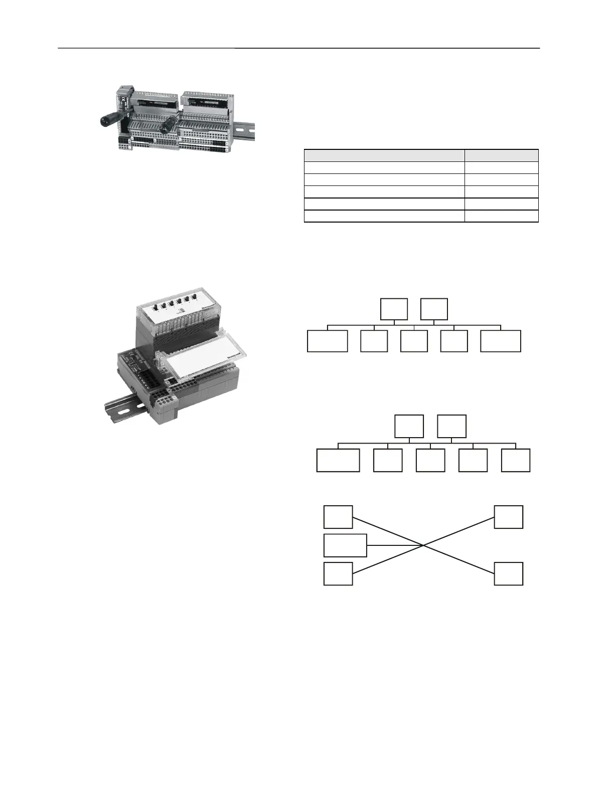
10. Lift the terminal block from the rail by inserting a screw-
driver tip into the two mounting feet - one after the other -
and lifting up the terminal block with small levering move-
ments.
Applying CARE Printout Labels
Fig. 37. XAL1 swivel label holder
Normally, CARE labels can be used on electronics modules.
When using electronics modules with manual override units,
CARE labels cannot be applied to the face of the manual
override unit. In this case, the XAL1 swivel label holder is re-
quired (package of 10). The XAL1 swivel label holder is
mounted to the terminal block as shown in Fig. 37.
LONWORKS Network Interface
Distributed I/O modules contain an FTT-10A Free Topology
Twisted Pair Transceiver allowing communication with other
devices on a L
ONWORKS network. FTT-10A transceivers
communicate at 78 Kbaud and provide transformer isolation
so that the bus wiring does not have a polarity; that is, it is not
important which of the two bus terminals are connected to
each wire of the twisted pair.
IMPORTANT
The L
ONWORKS transceiver can be affected by
electromagnetic fields generated by frequency con-
verters. If possible, locate frequency converters in a
different cabinet, or allow a min. distance of 18 inches
(50 cm) between frequency converters and their
respective cabling, and Distributed I/0 Modules.
FTT devices can be wired in daisy chain, star, loop or any
combination thereof as long as the max. wire length re-
quirements given below are met. The recommended con-
figuration is a daisy chain with two bus terminations. This
layout allows for max. bus length, and its simple structure
presents the least number of possible problems, particularly
when adding on to an existing bus.
NOTE: A doubly-terminated bus may have stubs of up to
10 ft (3 m) from the bus to each node.
Table 15. Doubly-terminated bus specifications
cable type max. bus length
Belden 85102 8,900 ft (2,700m)
Belden 8471 8,900 ft (2,700m)
Level IV, 22 AWG 4,600 ft (1,400m)
JY (St) Y 2x2x0.8 3,000 ft (900m)
TIA568A Categ. 5 24AWG, twisted pair 3,000 ft (900m)
NOTE: The cable types listed above are as recommended
by Echelon® in their FTT-10A User Guide. The cable
recommended by Honeywell is the level IV, 22 AWG,
solid core, non-shielded cable. Belden part numbers
are 9H2201504 (plenum) and 9D220150 (non-
plenum).
termination
module
termination
module
device
device device
device device
Fig. 38. Doubly-terminated bus configuration
(recommended)
Free topology requires only one bus termination and allows a
variety of bus configurations (see Fig. 39):
termination
module
device
device device
device device device
singly-terminated
device
device device
device
star
termination
module
Fig. 39. Possible bus configurations

 Loading...


