DISTRIBUTED I/O – PRODUCT DATA
23 EN0B-0090GE51 R0316
device
device
device
device
device
termination
module
termination
module
device
device
device
device
device
device
device
device
device
device
loop
mixed
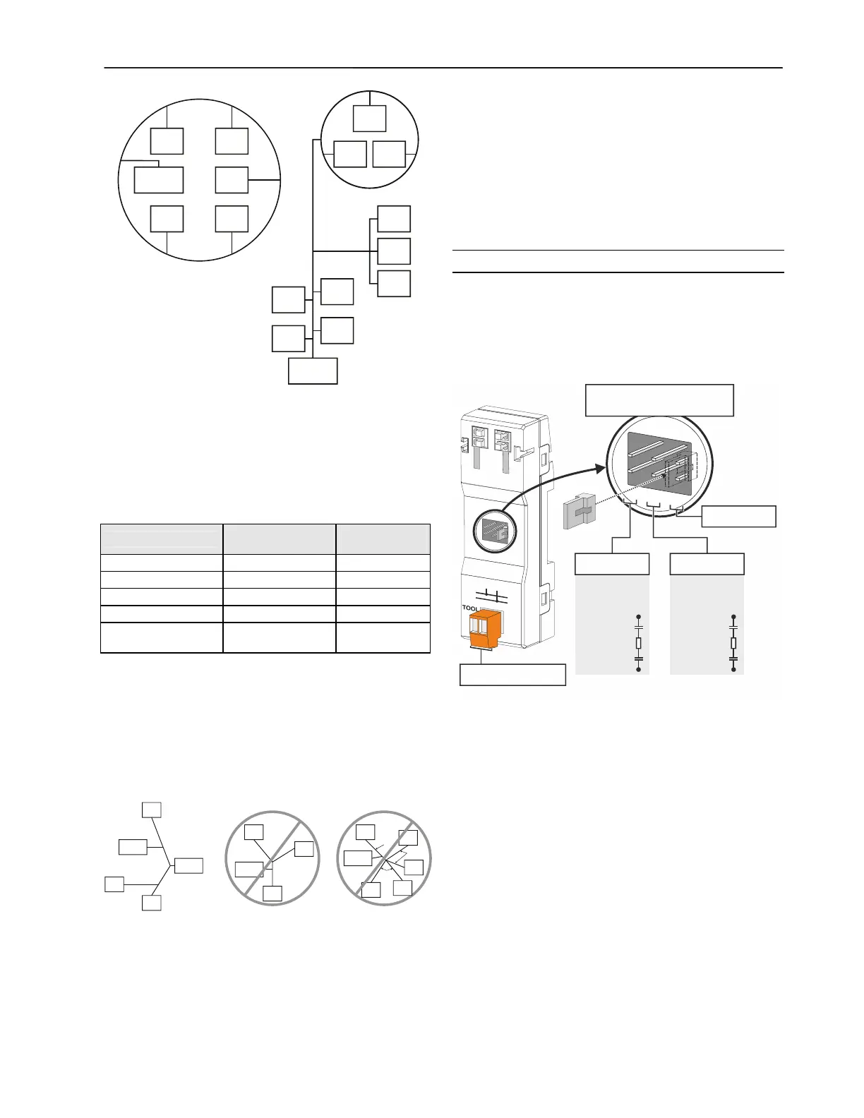
Fig. 40. Free topology examples
The FTT specification includes two components that must be
met for proper system operation. The distance from each
transceiver to all other transceivers and to the termination
must not exceed the max. node-to-node distance. If multiple
paths exist, the max. total wire length is the total amount of
wire used.
Table 16. Free topology (singly-terminated) specifications
cable type
max. node-to-
node distance
max. total wire
length
Belden 85102 1,650 ft (500 m) 1,650 ft (500 m)
Belden 8471 1,300 ft (400 m) 1,650 ft (500 m)
Level IV, 22AWG 1,300 ft (400 m) 1,650 ft (500 m)
JY (St) Y 2x2x0.8 1,050 ft (320 m) 1,650 ft (500 m)
TIA568A Category 5
24AWG, twisted pair
825 ft (250 m) 1,500 ft (450 m)
IMPORTANT
Do not use different wire types or gauges on the same
L
ONWORKS network segment. The step change in line
impedance characteristics would cause unpredictable
reflections on the bus.
Examples of allowed and not-allowed free topology layouts for
cable JY (St) Y 2x2x0.8 are shown in Fig. 41.
device
device
termination
module
CPU
device
termination
module
device
device
device
100 m
(328 ft.)
100 m
(328 ft.)
100 m (328 ft.)
100 m (328 ft.)
100 m
(328 ft.)
200 m
(656 ft.)
200 m
(656 ft.)
ALLOWED:
node-to-node = 200 m (656 ft.)
total wire length = 400 m (1312 ft.)
NOT ALLOWED:
node-to-node = 400 m (1312 ft.)
total wire length = 500 m (1640 ft.)
NOT ALLOWED:
node-to-node = 200 m (656 ft.)
total wire length = 600 m (1968 ft.)
termination
module
device
device
device
device
device
100 m
328 ft.
100 m
328 ft.
200 m
656 ft.
Fig. 41. Example of allowed/not-allowed free topology
layouts (max. node-to-node distance: 320 m, max. wire
length: 500 m)
NOTE: In the event that the limit on the total wire length is
exceeded, then FTT physical layer repeaters
(FTT 10A) can be added to interconnect segments
and increase the overall length by an amount equal
to the original specification for that cable type and
bus type for each repeater used. For example,
adding repeaters for a doubly-terminated bus using
JY (St) Y 2x2x0.8 cable increases the max. length
3000 ft (900m) for each repeater.
LONWORKS Bus Termination Modules
Depending upon the configuration, either one or two ter-
mination modules are required for terminating a L
ONWORKS
bus with FTT devices on it. The following L
ONWORKS
termination unit is available for this purpose:
XAL-Term2 L
ONWORKS connection and termination
module (see Fig. 42), which can be mounted on DIN rails
and in fuse boxes.
LONWORKS TERMINATION
PLUG-IN JUMPER
FTT/LPT
FREE TOPOLOGY:
52.3 OHM
100 μ
100 μ
52.3 Ohm
1
2
FTT/LPT
BUS TOPOLOGY:
105 OHM
100 μ
100 μ
105 Ohm
1
2
1
5
2
3
4
6
3
1
5
6
2
4
REMOVABLE SCREW-TYPE
2-POLE TERMINAL BLOCK
FTT/LPT BUS FTT/LPT FREE
PARK PO SITIO N
(NO TERMINATION)
Fig. 42. XAL-Term2
In the case of either a daisy chain or free-topology L
ONWORKS
bus layout, the max. lengths described above must be
adhered to.
Commissioning Distributed I/O Modules
The following refers to the commissioning of Distributed I/O
modules in conjunction with Excel 500 controllers into which
controller firmware version 2.04.xx has been downloaded.
Previous to controller firmware version 2.04.xx, Distributed I/O
modules were used only on a local L
ONWORKS bus connected
to a single Excel 500 controller. Concurrent with the release
of controller firmware version 2.04.xx is the release of the
XFL52xB Distributed I/O modules with updated firmware and
with a new Neuron chip which make them fully L
ONMARK-
compliant. This means that multiple Excel 500 controllers,
each with its own Distributed I/O modules, as well as third-
party L
ONMARK compliant devices, can coexist and inter-
operate on the same L
ONWORKS bus. Furthermore, the

 Loading...


