DISTRIBUTED I/O – PRODUCT DATA
EN0B-0090GE51 R0316 28
In the case of a power-up or reset, the service pin message
is delayed a random time between 1 and 5 seconds to
avoid an overload of a network management node
receiving these messages when a large number of
Distributed I/O modules are powered up simultaneously.
The service LED indicates the status of the Neuron® chip.
Normally, the service LED will blink a few times during the
power-up/reset phase and then remain off. During normal
commissioning, the service LED will stay on briefly and
then flash briefly before remaining off. The time required for
commissioning is variable, lasting from approximately 10 to
60 seconds, depending upon the amount of network
information being downloaded from the installation tool and
the installation tool itself. For additional information on
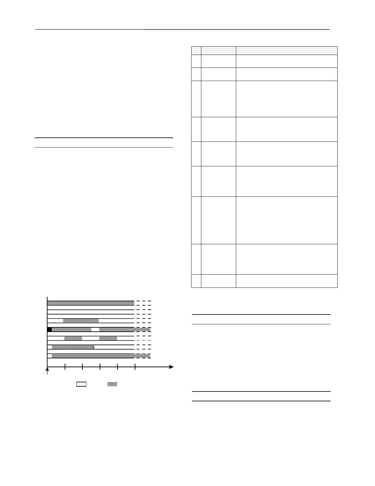
service LED behavior, see Table 21 and Fig. 45.
LONWORKS Service LED L2
This LED is used to diagnose the state of the Distributed
I/O module. In general:
The module is applicationless if the LED illuminates con-
tinuously.*
The module has an application but it is not configured if
the LED is blinking.
The module is running normally if L2 is off.
*Pushing the L
ONWORKS service button will force a new
commissioning of the module. While commissioning, LED
L2 continuously illuminates red for less than 1 minute and
then returns to the normal state (L2 = OFF).
A more detailed diagnosis can be carried out by observing
the duration of the ON and OFF states of the service LED
in connection with power ON / OFF. Fig. 45 illustrates the
different service LED behaviors. These are the most
common behaviors, but others are possible since the state
of the service LED is under firmware control and can be
affected both by hardware and software anomalies.
IMPORTANT
In Table 21, the words ”configured”, “unconfigured”,
“application”, and “applicationless” refer only to the
communication layer running on the Neuron® chip and not
to the controller application.
1 sec
1
2
3
4
5
6
7
ervice L
D Behavior
2 sec3 sec4 sec5 sec
Time
(at 10 MHz,
approx.)
Power
applied
to node
Continuous
* Does not scale with the Neuron chip.
Continuous
Continuous
Continuous
Repeated
Repeated*
see table
= ON = OFF
see table
Fig. 45. Service LED behavior
Table 21. Service LED behavior descriptions
context meaning
1
Power-up of
the node
Bad node hardware. For DI/O's, perform
the tests shown in the previous section.
2
Power-up of
the node
Bad node hardware. For DI/O's, perform
the tests shown in the previous section.
3
Power-up /
Reset of the
node
The module is applicationless. May be
caused by the Neuron chip firmware when
a mismatch occurs on application
checksums. This behavior is normal if the
application was exported to come up
applicationless.
4 Anytime
Possible corrupt EEPROM. For a Neuron
3150 Chip-based node, use a newly
programmed PROM, or EEBLANK and
follow bring-up procedure.
5 Anytime
The module is unconfigured. Connect the
Distributed I/O module to the CPU. The
CPU will configure the Distributed I/O
module.
6a
1
st
power-up,
application-
less firm-
ware state
exported
The OFF duration is approx. 1 sec. The
service LED should then turn ON and stay
on indicating an applicationless state.
6b
1
st
power-up,
unconfigured
firmware
state
exported
The OFF duration is 1-15 sec (depending
on the application size and system clock).
The service LED should then begin
flashing as in behavior 5, indicating an
unconfigured state. Connect the
Distributed I/O module to the CPU. The
CPU will configure the Distributed I/O
module.
6c
1
st
power-up,
configured
firmware
state
exported
The OFF duration is indefinite (1-15 sec to
load internal EEPROM; stays OFF
indicating configured state.) The module is
configured and running normally.
7 Anytime
The module is configured and running
normally.
Accessories, Standards, Ratings, and
Literature
Accessories
— XAL 1 Swivel Label Holder (required for Manual
Override Modules, package includes 10 XAL 1 swivel
labels).
— XAL 2 Cover Release Tool (required for opening the
module housing e.g. to set the module address using
the rotary HEX switch; package includes 20 XAL 2
Cover Release Tools).
— XAL-Term2 L
ONWORKS Connection and Termination
module (see Fig. 42 on page 23).
Approvals and Standards
CE and EN 50082-1
 Loading...


