EXCEL WEB CONTROLLER – INSTALLATION INSTRUCTIONS
EN1B-0256GE51 R0506C
7
recommendations provided in these installation
instructions.
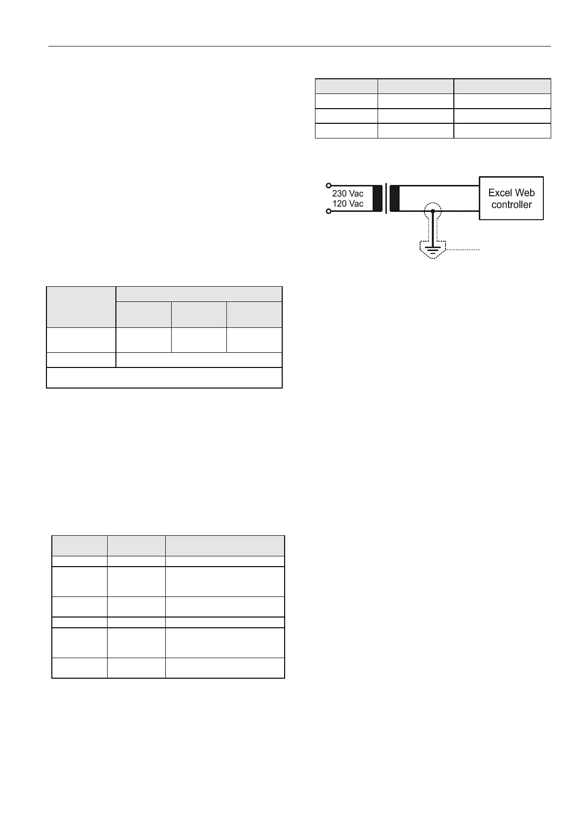
• Power supply: 24 Vac [±20%], 50 or 60 Hz, or
24...38 Vdc, galvanically isolated;
• Power consumption = max. 10 VA (USB unloaded);
• Excel Web® and 24 Vac field devices can obtain their
power from the same transformer;
• Several Excel Web controllers can share a single
common transformer. In this case, you must ensure
that terminal 1 of each of the Excel Web controllers is
connected to 24 V and terminal 2 is connected to the
minus pole (optionally, terminal 2 can additionally be
connected to the earth) (see also Fig. 12).
• The power supply LED (see section "Power Supply
LED" on page 4) indicates whether power is being
supplied.
• In the event you wish to connect one of the 24 Vac
pins to the earth ground, connect it via terminal 2 of
the lower removable terminal plug (see also Fig. 12).
Table 3. Cable sizing (use only copper cables)
cross-sectional area
type of signal
≤ 300 ft
(100 m)
≤ 550 ft
(170 m)
≤ 1300 ft
(400 m)
24 Vac power
supply
16 AWG
(1.5 mm
2
)
14 AWG
(2.5 mm
2
)
-
low-voltage*
14 – 18 AWG (2.5 – 0.75 mm
2
)
*0...10 V sensors, totalizers, binary inputs, 0...10 V signals
for actuators, etc.
Power is supplied via terminals 1 and 2 of the lower re-
movable terminal plug. The removable terminal plug per-
mits individual Excel Web controllers to be disconnected
from the power supply without disturbing the operation of
other devices powered by the same source.
NOTE: Do not reverse the polarity of the power connec-
tion cables, and avoid ground loops (i.e. avoid
connecting one field device to several controllers)
as this may result in short-circuiting.
Transformer Data
Table 4. 1450 series transformers data
part #
1450 7287
primary
side
secondary side
-001 120 Vac 24 Vac, 50 VA
-002 120 Vac
2 x 24 Vac, 40 VA, and
100 VA from separate
transformer
-003 120 Vac
24 Vac, 100 VA, and
24 Vdc, 600 mA
-004 240/220 Vac 24 Vac, 50 VA
-005 240/220 Vac
2 x 24 Vac, 40 VA, and
100 VA from separate
transformer
-006 240/220 Vac
24 Vac, 100 VA, and
24 Vdc, 600 mA
Table 5. Overview of CRT Series AC/DC current
transformer max. AC current max. DC current
CRT 2 2 A 0.5 A = 500 mA
CRT 6 6 A 1.3 A = 1300 mA
CRT 12 12 A 2.5 A = 2500 mA
2
1
24 Vac
primary
voltage
transformer
24 V~
(-)
optional
Fig. 12. Connection of Excel Web
Lightning Protection
Please contact your local Honeywell representative for
information on lightning protection.
RIN-APU24
The RIN-APU24 Uninterruptable Power Supply can be
directly wired to an Excel Web.
See RIN-APU24 Uninterruptable Power Supply – Mounting
Instructions (EN0B-0382GE51) for a detailed wiring
diagram.
LONWORKS COMMUNICATIONS
General Information
The Excel Web controller is equipped with a free-topology
transceiver (FTT10A or FT-X1) for communication (at a
data transmission rate of 78 Kbaud) on L
ONWORKS®
networks (using the LonTalk protocol).
The L
ONWORKS network is insensitive to polarity,
eliminating the possibility of installation errors due to
miswiring.
Different network configurations (daisy-chain, loop, and star
configurations, or any combination thereof) are possible
(see also Excel 50/500 L
ONWORKS Mechanisms Interface
Description, EN0B-0270GE51).
Connecting to the LONWORKS Network
IMPORTANT
Do not bundle wires carrying field device signals or
L
ONWORKS communications together with high-
voltage power supply or relay cables. Specifically,
maintain a min. separation of 3 inches (76 mm)
between such cables. Local wiring codes may take
precedence over this recommendation.
IMPORTANT
Try to avoid installing in areas of high electro-
magnetic noise (EMI).
 Loading...


