52 107062-12 EN FR26 GLO 501 Printed in France
Test Contacts
Test contacts may be used for additional external relay checking. When the link between the two contacts is
open, the light curtain is in the red condition and R2 and R4 (LEDs on receiver) are illuminated. To return to
the green condition, the link between the contacts must be reestablished.
C4, C5: For FF-SB Original Series or FF-SB CE in factory setting (see figure 3-4).
C4, B3: For FF-SB CE Series in cycle start mode (see figure 3-5).
Factory Settings (receivers only)
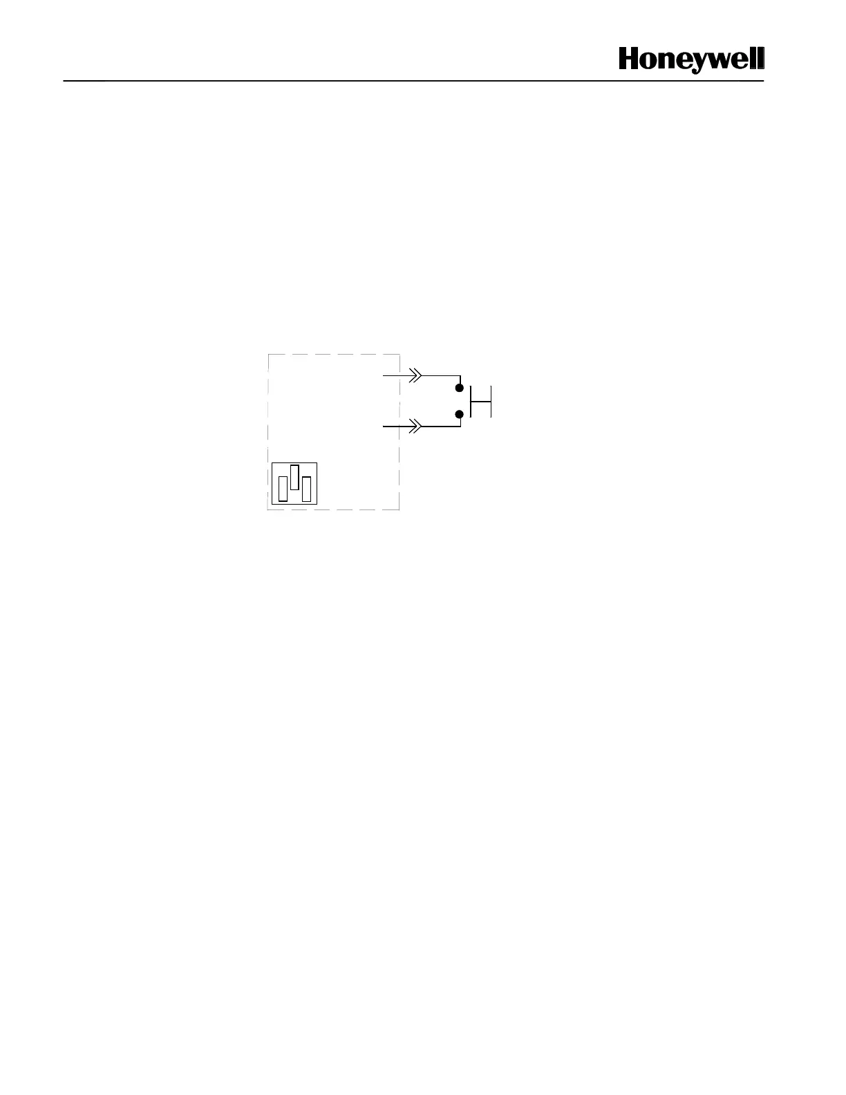
Figure 3-4 Replacing FF-SB Original Series with CE Version (factory setting)
Optional test
function
NOTICE: Points C4 and C5 are jumpered
if the optional test function is not used
(no voltage is applied).
RECEIVER
C5
C4
● ● ●
● ● ●
● ● ●
Jumper Link position
on the Receiver
Power Board (factory
setting)

 Loading...


