107062-12 EN FR26 GLO 501 Printed in France 61
IMPROPER RELAY OUTPUT BOARD MAINTENANCE
After a period of extended operation, it is possible that a switching relay can malfunction such that it remains
stuck of fused in the closed position following a breach of the light curtain’s protection field and the shutdown
of the machine.
In the case of such a relay malfunction, the machine will not restart following the clearing of the protection
field (and pressing of the restart button when in manual restart mode) and the following warning diagnostic
LED condition will be seen on the light curtain receiver unit:
R2 (red) ON R1 (red) OFF R4 (yellow) FLASHING
It is essential to immediately replace the relay board upon the first occurrence of a stuck or fused relay and
the activation of the receiver operation status LED R2.
Failure to comply with these instructions will result in death or serious injury.
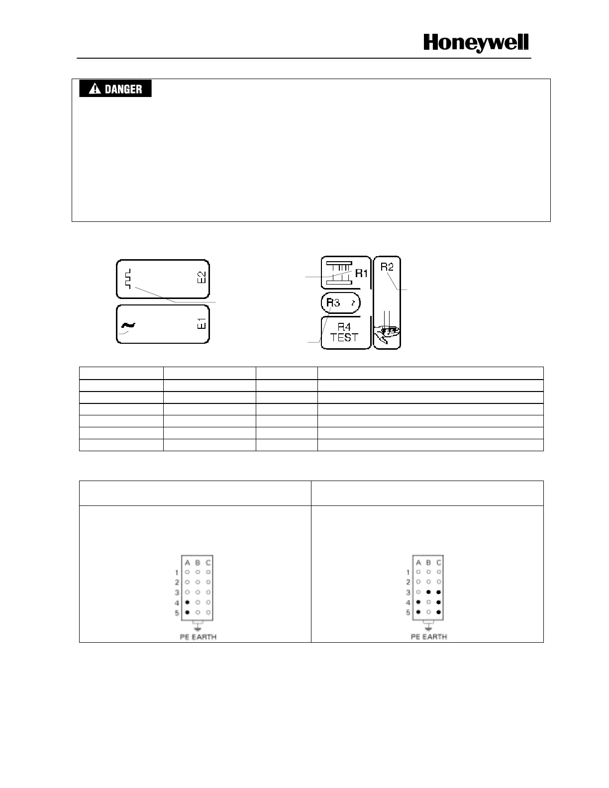
Figure 4-2 Emitter and Receiver LEDs
Emitter LEDs Receiver LEDs
LED Location Color Function
E1 Emitter Yellow Supply voltage on
E2 Emitter Yellow Synchronization beam detection
R1 Receiver Red Marginal signal detection
R2 Receiver Red Interrupted sensing field
R3 Receiver Green Clear sensing field
R4 Receiver Yellow Illuminated = test, Flickering = restart required
Test Plug Construction (see troubleshooting flow diagram, sheet 1 of 2)
Emitter Female Plug Connector
FF-SBZ1721137
Receiver Female Plug Connector
FF-SBZ1721202
Using Female Plug Connector FF-SBZ1721137,
connect pins A4 and A5 to supply voltage and the
ground pin to earth ground.
Using a Female Plug Connector FF-SBZ1721202,
connect pins A4 and A5 to supply voltage and the
ground pin to earth ground. Also jumper the following
pins: C4, C5, B3 and C3.
Emitter Board Visual Test (see troubleshooting flow diagram, sheet 2 of 2)
1.
Clean the front lens window of the emitter.
2. Place your eye against the emitter front lens window and observe the presence of a low energy red light
(a spot) in the middle of each beam (except synchronization).
3. If you can observe the presence of this red light, the emitter is working correctly. If you cannot, replace
the faulty emitter board.
Supply voltage
Synchronization
beam
Marginal signal
Clear sensing
field
Interrupted
sensing field

 Loading...


