MU1H-1515GE23 R0709 4 Honeywell GmbH
GB
1. Safety Guidelines
1. Follow the installation instructions.
2. Use the appliance
• according to its intended use
• in good condition
• with due regard to safety and risk of danger.
3. Note that the appliance is exclusively for use in the
applications detailed in these installation instruc-
tions. Any other use will not be considered to comply
with requirements and would invalidate the
warranty.
4. Please take note that any assembly, commis-
sioning, servicing and adjustment work may only be
carried out by authorized persons.
5. Immediately rectify any malfunctions which may
influence safety.
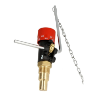
2. Functional description
The Combustion Regulator controls combustion by
adjusting the supply of air to a boiler. The intergral ther-
mostat measures the temperature in the heat gene-
rator and in relationship to the temperature regulates a
lever with chain linkage to control the air inlet to the
solid fuel boiler by opening or closing the air flap.
3. Application
For solid fuel and multi-fuel heating installations to DIN
4751
The FR124 Combustion Regulator may in particular
not be used in the following cases:
• Explosive environments. Sparks can lead to defla-
gration, fire or explosions during operating in explo-
sive areas.
4. Technical data
5. Scope of delivery
The FR124 Combustion Regulator consists of:
• Housing
• Adjuster knob
• Immersion pocket
• Lever rod
• Chain
• Wax thermostat
• Return spring
6. Options
7. Assembly
7.1 Installations Guidelines
• Horizontal or vertical installation
• Install Combustion Regulator in the water cycle of
the boiler
• Only install it in the screw socket intended for this
purpose
7.2 Assembly instructions
1. Seal threaded joint with hemp or Teflon tape.
2. Screw immersion tube (thread T
3
/
4
) into the
threaded socket of the boiler
3. Secure the lever rod
4. Secure chain to the lever rod and the inlet air flap
o The chain hangs free and the lever rod moves
freely when the adjuster knob is turned
8. Commissioning
8.1 Calibrating the Combustion Regulator
1. Heat up the boiler with manually opened inlet air flap
2. Set the adjuster knob on the Combustion Regulator
to "60"
3. Once the water temperature has reached and main-
tained 60 °C adjust the chain length so that door 2
remains open.
Setting range 30...90 °C
Permissible sensor
temperature
max. 115 °C
Ambient air temperature max. 70 °C on adjuster
knob
Connection size T 3/4"
Chain length 1.2 m
Chain load 100...600 g
Immersion tube length 53 mm
FR124-3/4A = Standard version
 Loading...