5.7 Wiring to a Fire Control Panel
The flame detector can be connected to a fire control panel using the current increase principle.
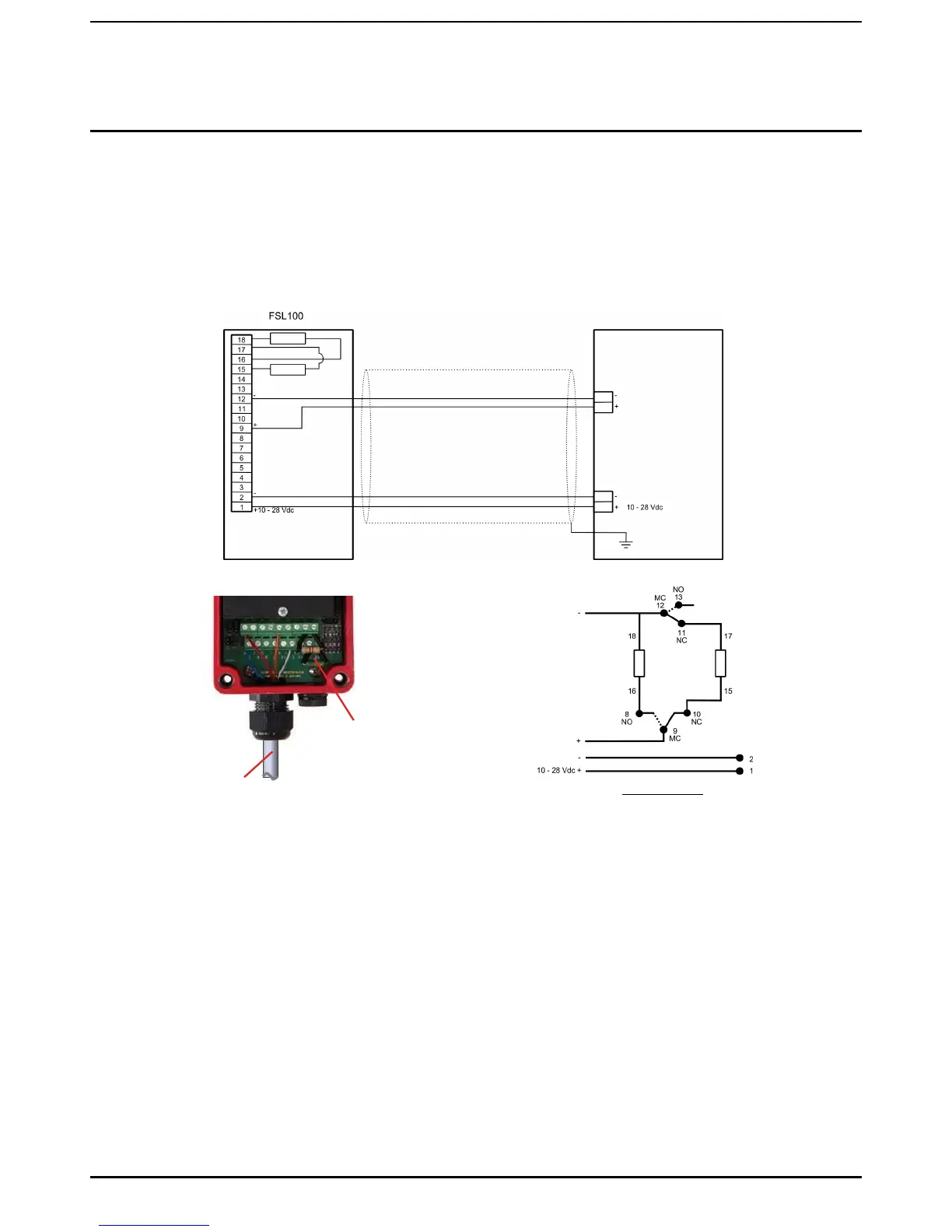
The flame detector is connected to the fire panel with 3 or 4 core cables, i.e. 2 cores for the power supply and 1 or 2 cores for
the loop. An additional core for the manual self-test may be used (see the FSL100 Terminal Connection Diagram).
The end of line resistor (EOL) is placed between the terminals 15 and 17. The alarm resistor (AL) is placed between terminals
16 and 18. The end of line and alarm resistors should be adapted to the fire control panel. They are approximately the same
size resistors that are used when connecting a manual call point to a fire control panel.
Controller
Alarm
EOL
Loop
Loop
Alarm
Alarm
Power
Screen end
isolated from
detector and
earth (ground)
Screen end
connected to
system earth
(ground)
Screened cable
Power On, Normal
Figure 11. FSL100 to Controller Wiring
Operating Principle:
The loop uses the alarm contact and the fault contact of the flame detector plus two resistors. In the event of a detector fault a
wire breakage is simulated. In the event of a fault followed by an alarm, a current Vn/AL is flowing through the loop. Thus an
alarm ‘overrides’ a fault signal, as can be seen in the figure.
Notes:
1. Please consult the fire control panel manufacturer for the values of the Alarm and EOL resistors.
2. The alarm and EOL resistor must be rated 2 W minimum each, and the total power dissipation of both alarm and EOL
resistor should not exceed 2 W. Use heat shrink tubing to insulate the legs of the EOL and the AL resistor when in-situ.
3. Do not connect more than one flame detector to a loop.
 Loading...


