FSL100 Series Flame Detectors
Technical Handbook
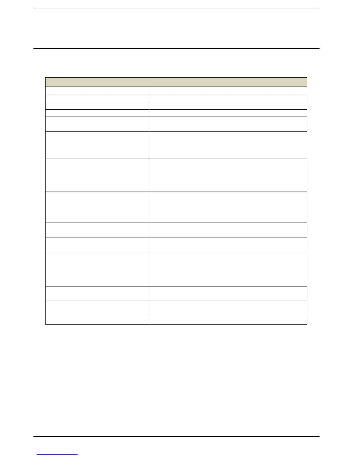
FSL100 General Specifications
Selectable LEDs and relays latching/non latching, factory
setting: latching
- a fire control panel by means of end of line (EOL) and alarm
resistor (current increase)
- a device that can take relay outputs
- a PLC with a 0–20 mA input
End Of Line And Alarm Resistor
To match the fire control panel, free terminals dedicated for
the resistors are available
Note: the alarm and EOL resistors must be rated 2 W minimum
each and the total power dissipation of both alarm and EOL resistors
should not exceed 2 W
continuous green: normal operation
continuous yellow: fault (blinking yellow: repeated self-test after a
self-test fault)
continuous red: alarm
De-energized during normal operation, no alarm, SPDT, 30 VDC –
2 A, 60 W max.
Energized during normal operation, no fault, SPDT, 30 VDC – 2 A,
60 W max.
Standard available 0-20 mA (stepped, sinking, non-
isolated) 0 mA power fault / microprocessor fault
2 mA optical fault
4 mA normal operation
20 mA Alarm
Maximum Range (IR)
(to alarm <10 s for a 0.1 m
2
n-heptane fire)
35 m/115 ft. (FSL100-IR3)
Maximum Range (UV and UVIR)
(to alarm <10 s for a 0.09 m
2
n-heptane fire)
23 m/75 ft. (FSL100-UV and FSL100-UVIR)
 Loading...


