Do you have a question about the Honeywell Notifier FST-951 and is the answer not in the manual?
Wire the sensor base as shown in the wiring diagram for installation.
Set the desired sensor address using the rotary dial switches.
Install the sensor into the base by pushing and turning clockwise.
Apply power to the control unit and activate the communication line after installation.
Test the sensor(s) as described in the TESTING section of the manual.
Use the optional test magnet to activate the sensor's test feature.
Apply heat using a hair dryer to the sensor for testing.
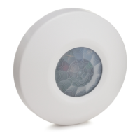
The FST-951 series of intelligent programmable temperature sensors, including models FST-951, FST-951-IV, FST-951R, FST-951R-IV, FST-951H, and FST-951H-IV, are designed to provide reliable fire detection in open areas. These sensors utilize a state-of-the-art thermistor sensing circuit, enabling a fast response to changes in temperature. They are approved by UL 521 for heat detectors and are capable of providing protection with a 50-foot spacing.
These intelligent temperature sensors are field programmable, meaning their operational mode can be configured through the Fire Alarm Control Panel (FACP). They can be set to operate in one of three primary modes:
It's important to note that the availability of these programming features may vary depending on the specific control panel used. In panels where programmable features are not available, the FST-951 and FST-951-IV models will default to a 135°F fixed heat detector. The FST-951R and FST-951R-IV will default to a 135°F fixed heat detector with rate-of-rise functionality. The FST-951H and FST-951H-IV will default to a 190°F high temperature heat detector.
The FST-951, FST-951R, and FST-951H models support FlashScan® protocol mode, while the FST-951-IV, FST-951R-IV, and FST-951H-IV models support either FlashScan or CLIP (Classic Loop Interface Protocol) mode. These intelligent programmable temperature sensors require compatible addressable communications to function correctly and must be connected to UL listed-compatible control panels.
The sensors are designed for ease of installation and monitoring.
Regular testing and cleaning are essential to ensure the continued optimal performance of the FST-951 series sensors.
Proper installation and maintenance, in compliance with the National Electrical Code and local codes, are vital for the system's reliability. The use of proper wire gauges and color-coded wiring is recommended to minimize mistakes and facilitate troubleshooting.
| Operating Voltage Range | 15 to 32 VDC |
|---|---|
| Weight | 0.5 lbs (0.23 kg) |
| Color | White |
| Humidity | 10% to 93% RH non-condensing |
| Height (including base) | 51 mm (2.0 in) |
| Certifications | UL, ULC, CSFM, FM |
| Material | Plastic |
| Standby Current | 200µA @ 24 VDC (one communication every 5 seconds with LED enabled) |