HA40 4-Channel Controller
HA40 Technical Manual
2-2
2 Operation
The HA40’s graphic LCD displays monitored data. The 5-button
keypad and the display serve as the system’s operator interface. All
HA40 configuration variables are entered using this operator interface
through SETUP menus accessed by pressing Edit from either data
screen. This Setup mode may be exited manually by pressing Next,
or automatically when no keys are pressed for 5 minutes. Alarm relays
and front panel alarm LED indicators remain active during the Setup
mode. Alarm LED’s flash upon new alarms and become steady after
Acknowledged by pressing the Alarm Reset key. A SECURITY menu
offers a password feature to prevent tampering with HA40 parameters.
A “sign-on” screen appears briefly after power is applied that indicates
what type of input / output options are configured with the unit.
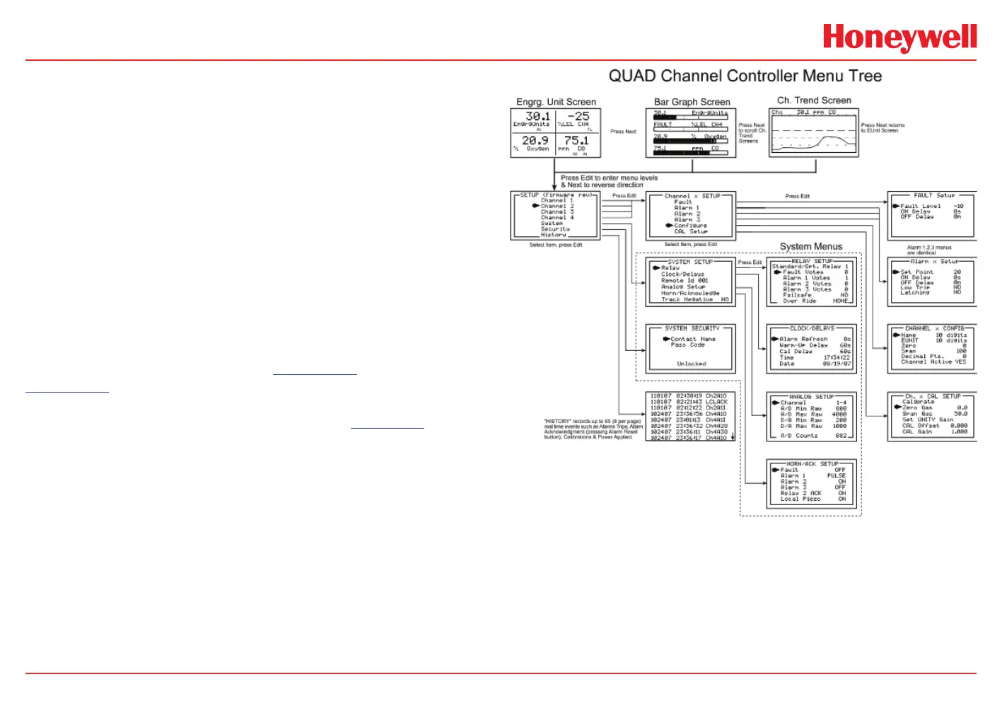
2.1 Setup Menu Conguration
Variables inside the CHANNEL (see Section 2.2) and SYSTEM (see
Section 2.3) menu trees allow HA40 configuration for a wide range of
monitoring applications. Select the desired menu by scrolling with Up/
down arrows and then Edit to enter each menu. Figure 2-1 illustrates
the menus tree for configuring Channel and System specific variables.
Channel variables affect only the specific channel selected while
System variables are related to features not specific to any channel.
 Loading...