Electrical installation
25
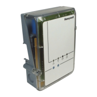
5.2.1. Further components for the boiler
feedback
► Install further components (e.g. relay module
HC60NG/R6660D) in accordance with the enclosed
installation instructions.
6. Electrical installation
DANGER
Danger to life through electric
shock!
Contacts that are open are live.
► Ensure that the device is de-
energised.
► Have all the work carried out by
authorised qualified personnel.
► Observe the valid IEE regulations
during the installation.
WARNING
Damage to exposed components!
Destruction of the electronic
components through electrostatic
discharges.
► Do not touch the components.
► Touch an earthed piece of metal to
discharge static electricity from your
body.
6.1. Electrical installation of Universal
Mixing Valve Controller HM 80
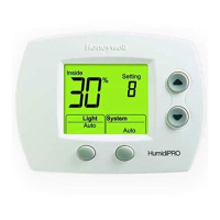
6.1.1. Opening the housing
► Open the housing as shown in Fig. 5 on the fold-out page.
6.1.2. Permissible cable types and lengths
Power and pump connection 230 V~
Outer cable
diameter
Min. 5.0 mm/max. 10 mm
Cable length Max. 100 m
Terminal range 0,3–1,6 mm²
Stripping length 6 mm
Cable type NYM-J
Flow temperature sensor
Outer cable
diameter
Min. 5.0 mm/max. 10 mm
Cable length Max. 100 m
Terminal range 0,3–1,6 mm²
Stripping length 7 mm
Cable type Flexible/Rigid
Earthed connection
Terminal range 0,3–2,7 mm²
Stripping length 8 mm
Tab. 2: Permissible cable types and lengths
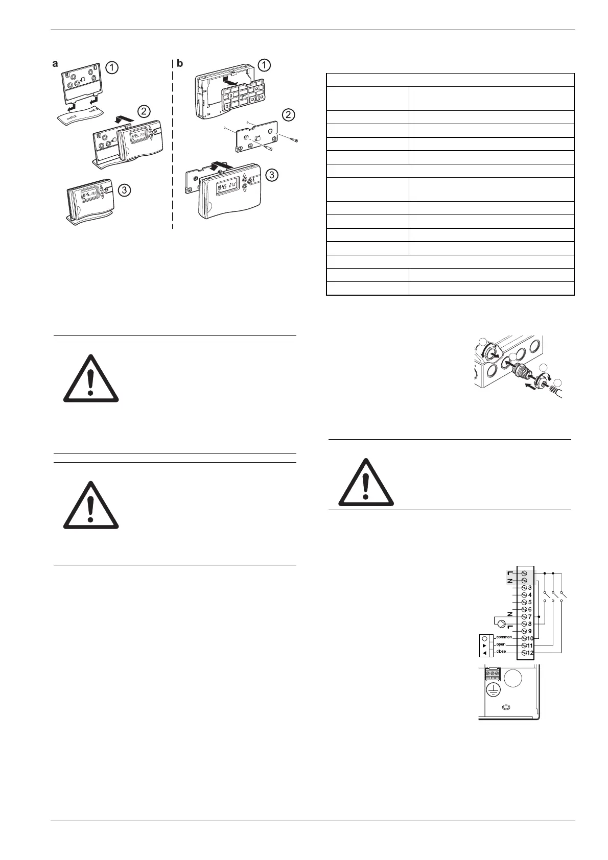
6.1.3. Securing cables with a cable gland
► Secure the cables with the
enclosed Eurofix cable glands in
accordance with the following
graphic.
► Observe the installation
instructions for Eurofix.
4
1
2
3
6.1.4. Connecting a power cable (230 V~)
DANGER
Danger to life through electric
shock!
Contacts that are open are live.
► Ensure that the device is de-
energised.
► Select a suitable cable in accordance with Table 2 for the
power supply.
► Strip the connections 7 mm.
► Connect the cable to the
connector in accordance with the
graphic (see fold-out page,
Fig. 3 (8)).
► Connect the earthed connection
(PE conductor) in accordance
with the following graphic.
► Secure the cable with the cable clamp.
 Loading...