HM700A1000
33-00118—01 12
START UP
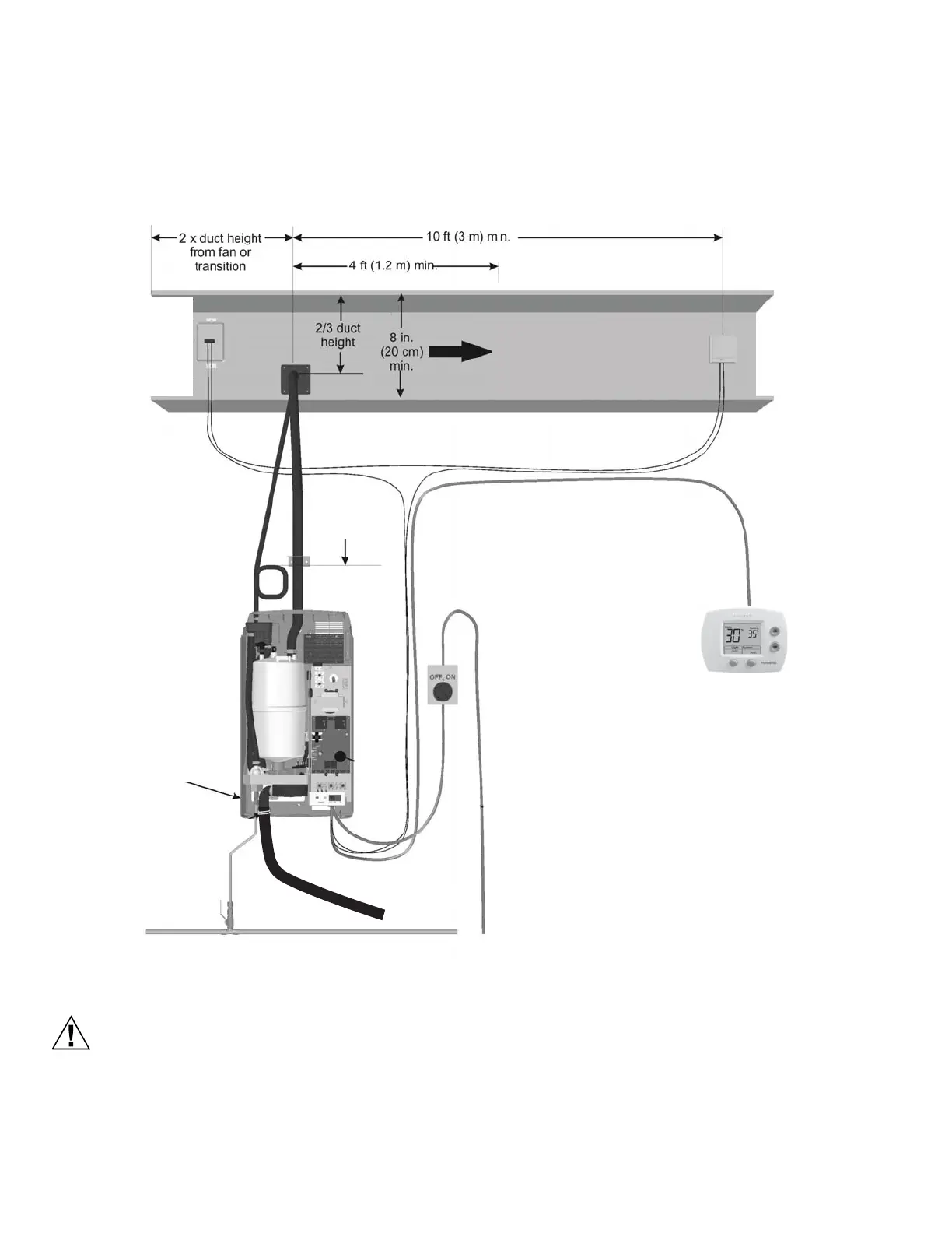
Installation Check
Before turning on power to the HM700, inspect the installation to ensure that it was carried out correctly.
Fig. 18. Installation check.
Equipment Damage Hazard
Do not leave the On/Off/Drain switch in the drain
position for more than one complete drain cycle. The
drain valve solenoid may heat up and result in damage
to the valve and its wiring.
Do not attempt to drain with no water in system.
On/Off
The HM700 is factory-configured to operate as an On/Off
humidifier. It will run when 24 VAC from terminal 1 is fed back
into terminal 2 through an On/Off humidistat and other
security devices in series.
Fused Disconnect
Correct voltage / amps /
phase per spec label
(optional)
Mounting
- Unit level
- Screws into
structural member
Steam Line
- Adequate slope
- No restrictions
- No kinks in hose
- Condensate traps
on long runs
High Limit
On/Off
(optional)
In series between
terminals 1 and 2.
Jumper between terminals
1 and 8 must be removed.
Note:
U or HUM terminals in series
between terminals 1 and 2
Humidity Control
in return duct or
location which
represents humidified
space (no drafts, not
by door, not by
diffuser)
Air Proving
(optional)
In series between
terminals 1 and 2.
Jumper between
terminals 1 and 8
must be removed.
1/2 in. line (minimum) to within 4 ft (1.2 m)
30-100 PSIG
Spec Label
Air Gap
P Trap
with 12 in (30 cm)
minimum drop
Bend, or other
obstruction
 Loading...