- 2 -
DT-600 ALARM SEQUENCE (MAP PROCESSING)
DT-600 sensors use the following event sequence to determine an alarm.
NOTE: If eight microwave (and no PIR) events occur within one
minute, the INFORMER circuit will disable itself for eight minutes.
This feature allows the INFORMER circuit to compensate for
temporary environmental disturbances. If a PIR event occurs
during the disable period, the microwave is automatically reset.
IMPORTANT: If the LEDs are enabled by Remote LED Enable
and an INFORMER condition occurs, the LEDs will flash the
INFORMER trouble code until the condition is cleared, even if the
LEDs are subsequently remotely disabled.
•
•
MICROWAVE RANGE ADJUSTMENT
DT-600 sensors are equipped with a microwave range adjustment
thumbwheel (R69). Set the range at MINIMUM by turning the
thumbwheel all the way to the left. (See Figure 3).
As you perform the walk-test, gradually turn the thumbwheel to the
right to increase the microwave sensitivity until the desired range
is obtained.
WALK-TEST
Walk across the protected area at the ranges to be covered. Two
to four normal steps make the diagnostic LEDs light, and indicate
an alarm condition. When there is no motion in the protected area,
all three LEDs should be off.
When an INFORMER condition occurs, and the jumper at position
W3 is not installed, the trouble output is active until the INFORMER
condition is cleared, and the LEDs display an INFORMER trouble
code. The DT-600 immediately performs a self-test to determine if
the problem is internal.
If a self-test error is detected, the self-test LED pattern replaces
the INFORMER LED pattern. (Refer to the Troubleshooting
Matrix on page 3.)
LED DISABLE
To disable the diagnostic LEDs and alarm LED, remove the
jumper from position W2 on the PCB. (See Figure 3.)
If the microwave technology malfunctions (determined by a self-test), the sensor reverts to a PIR sensor.
If no self-test error occurs, the sensor continues to display the
INFORMER LED pattern. The problem is misapplication. Walk-
test the DT-600 to pinpoint the cause.
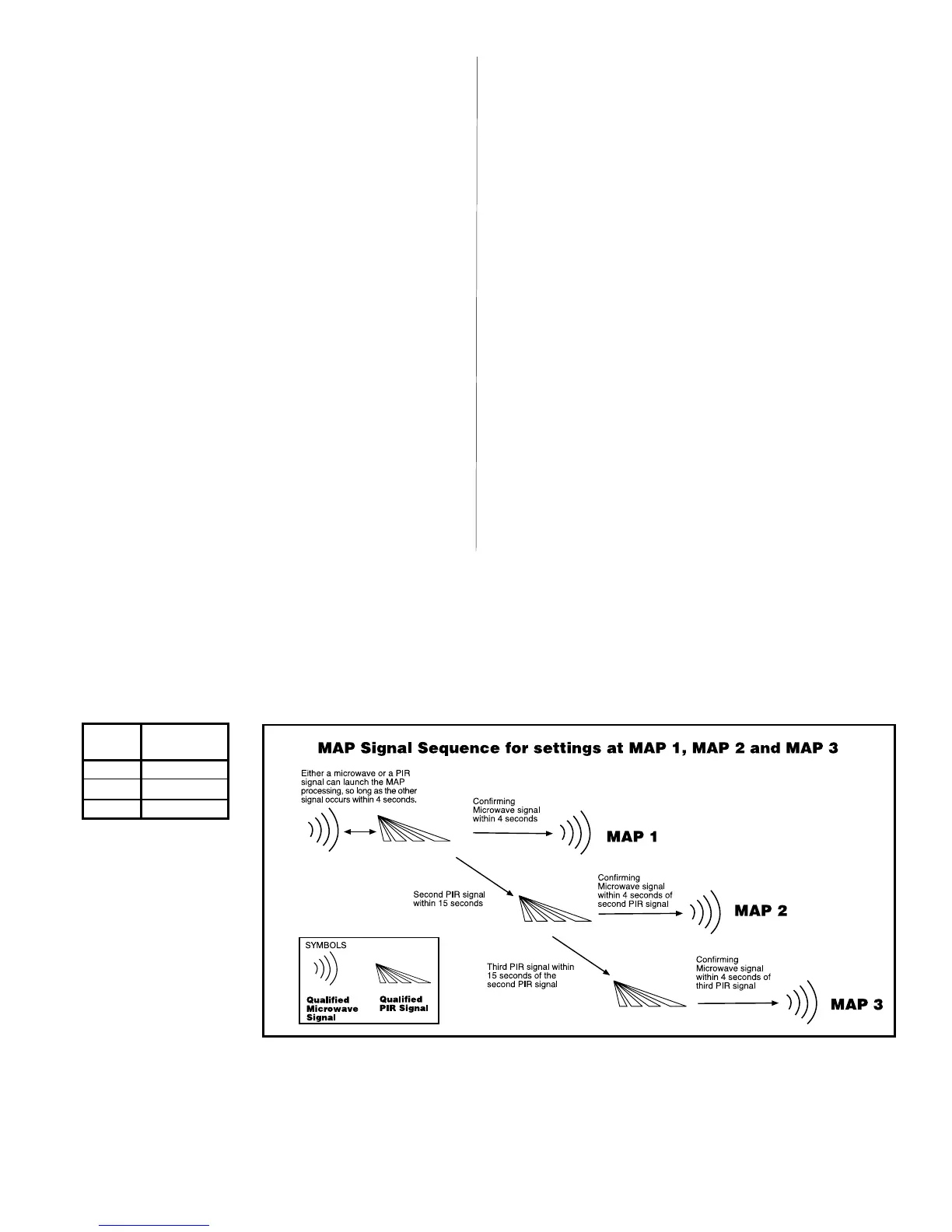
M.A.P.
Processing
W1 Jumper
Position
1
2
3
On pins 1 & 2
On pins 2 & 3
Removed
Figure 4
MAP Signal Sequence
INFORMER CIRCUIT
The INFORMER circuit counts the number of events registered by
both the microwave and PIR technologies, and uses the resulting
ratio to determine if either technology is misapplied or working
properly.
The INFORMER ratio is preset at 32 to 1. This ratio means that before
one technology registers 32 events, the other must register at least
one event. If it does not, trouble will be signaled.
 Loading...