Honeywell IS-310 Request-to-Exit Sensor
1. Description
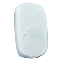
The IntelliSense® IS-310 is a Request-to-Exit Passive
Infrared (PIR) sensor. Mounted near an exterior door
inside a building with an access control system, the
sensor provides free exit to individuals within the
building without causing an alarm.
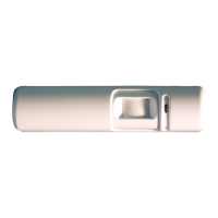
The parts of the IS-310 are shown below.
310-001-V0
PIR
DIP
SWITCH
ON
654321
TERMINAL
BLOCK
ROTATION
LOCKING
SCREW
LED
(UNDER
PIR COVER)
+
+
+
+
+
+
+
+
CEILING
WALL
S
L
S
L
2. Mounting Location
The IS-310 can be mounted on the wall or ceiling.
MOUNTING HEIGHT
7 TO 15 FEET
(2.13 TO 4.57 METERS)
15 FT
(4.57 M)
MAX.
7 FT
(2.13 M)
MIN.
RTES-002-V0
NOTE: If the maximum range of 8.4’ (2.6m) is desired,
the mounting height must be at the maximum (15’ or
4.57m).
Choose a mounting location that:
• Gives the sensor a clear line-of-sight to every part
of the detection area. Infrared energy cannot
penetrate solid objects; if the PIR cannot detect
movement, the sensor will not activate.
• Does not place the sensor directly across from one
or more windows.
• Is away from moving machinery, fluorescent lights
and heating and cooling sources.
The mounting locations available for a request-to-exit
sensor can be fairly limited. You may find that it is
impossible to avoid a source of false detection within
the IS-310’s detection pattern. In that case block the
sensor’s view of that portion of the pattern by adjusting
the shutters as described in section 7.
3. Mounting Procedure
To mount the sensor, do the following:
1. Open the sensor housing by pressing on the latch
with a screwdriver. This latch is located on the end
of the sensor nearest the lens. Pull the cover up
and away from the sensor’s base.
2. Loosen rotation locking screw two (2) turns (do not
remove). Then, remove PCB assembly from the
backplate of the sensor.
3. Insert the wiring into one of the wire channels on
the sensor’s backplate.
4. Securely affix the sensor’s backplate to the wall or
ceiling using 2 #6 X 3/4 inch (3.5 X 19 mm) screws
provided.
5. Reinstall the PCB assembly and adjust for short or
long range as described in section 6. Then, tighten
rotation locking screw.
RTES-001-V0
SCREW
#6 x 3/4"
(3.5 x 19mm)
(TYP.)
WIRE
CHANNELS
4. Input/Output Description
The IS-310 inputs and outputs are as follows:
V+/V–: Connects to AC or DC power (12 to 28 volts).
Relays: Input/Outputs for the unit’s dual double
pole/double throw relay. The relay may be used to
control a magnetic lock or signal an access control
system. All relay connections (common, normally
closed, and normally open) for both sets of contacts
are available on the terminal block.
NOTE: Relay timer settings and the reset mode
setting affect operation of this relay (see switches 3,
4, 5, and 6 in DIP Switch Settings).
CAUTION: When using the IS-310 to control a
magnetic lock, we recommend that an electric
suppressor such as S-4 (supplied by Northern
Computers) or EL-EDS (manufactured by EDCO) be
used to provide transient protection for the magnetic
lock and relay contacts. Install the suppressor across
the leads connected to the lock as close as possible
to the lock.
5. IS-310 Wiring
Wire the sensor as shown in the illustration.
+
+
+
+
+
+
+
+
NCCNO
NCCNO
310-002-V2
ALARM RELAY
CONNECT TO MAGNETIC LOCK,
ACCESS CONTROL SYSTEM,
OR ALARM SYSTEM*
ALARM RELAY
CONNECT TO MAGNETIC LOCK,
ACCESS CONTROL SYSTEM,
OR ALARM SYSTEM
V+ V-
CONNECT TO
AC OR DC
NOTE: USE 18-22 AWG WIRE
6. Long Range/Short Range Adjustments
The IS-310 can be set to detect individuals at either a
long range (several steps from the door) or at short
range (immediately in front of the door). If the building
includes a lengthy approach to the exit doorway and no
other foot traffic in the area, choose the long-range
setting.
NOTE: If the maximum range of 8.4’ (2.6m) is desired,
the mounting height must be at the maximum (15’ or
4.57m).
SHORT RANGE
LONG RANGE
RTES-003-V0
Choose between long- and short-range detection patterns
To set the range length:
1. Loosen the rotation locking screw.
2. Turn the PCB in its rotating base until the arrow on
the base is aligned with the appropriate notch on
the baseplate. If the sensor is ceiling mounted,
choose between the notches with the “Ceiling”
label. If the sensor is wall mounted, choose
between the notches with the “Wall” label. The
arrow on the mounting base (or back plate) needs