EasyManua.ls Logo

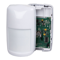
Honeywell IS3016A User Manual

Honeywell IS3016A
6 pages
To Next Page IconTo Next Page
Page #1 background imageLoading...
Page #1 background image
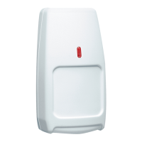
IS3016A Passive Infrared Motion Sensor with Anti-Mask - Installation Instructions
QUICK LINKS
Mounting Location Guidelines
Open the Sensor
Mount the Sensor
Sensor Components and Settings
Wire the Sensor
Wiring Examples
Walk Test the Sensor
Detection Patterns
Remote LED Enable
Relay Operation
Mask Condition
Troubleshooting
Sensor Specifications
Accessories
Approval Listings
1. Turn the arrow to point to the Unlock symbol.
2. Press firmly on housing latch.
3. Gently separate the front and rear housing.
[EN] = approved installation.
Mounting location guidelines:
The maximum range is obtained at a mounting height
of 2.3m (7’ 6”).
Allow a clear line-of-sight to all areas to protect.
Avoid mounting anything within 30cm (12”) in front of the sensor.
Do not directly face windows.
Avoid close proximity to moving machinery, fluorescent lights, and
heating/cooling sources.
Not for use in applications with pets.
Questions and Answers:

Honeywell IS3016A Specifications

General IconGeneral
MaterialPlastic
ColorWhite
TypeMotion Detector
Mounting Height7 ft to 9 ft (2.1 m to 2.7 m)
Power Supply9-15 VDC
CompatibilityHoneywell and other security systems
Dimensions4.6 in x 2.4 in x 1.8 in

Summary

Installation Preparation

Mounting Location Guidelines

Guidelines for optimal sensor placement, including range, line-of-sight, and avoiding obstructions.

Opening the Sensor Housing

Steps to unlock and separate the front and rear housing of the motion sensor.

Sensor Mounting and Configuration

Mounting Holes, Tamper Plate, and EOL Settings

Details on mounting holes, tamper plate requirements, and EOL resistor configuration.

Look Down and Anti-Mask/LED Settings

Configuring the look-down feature and Anti-Mask/LED settings via DIP switches.

Wiring the Sensor

Wire Gauge and Terminal Connections

Specifications for wire gauge and connection points for sensor wiring.

Wiring Details and Operation

Wiring Details and Examples

Guidelines on polarity, EOL resistor usage, and configuration examples for single/dual loops.

Walk Test Procedure and LED Indicators

Procedure for performing a walk test, understanding LED indicators, and test duration.

LED Behavior Notes During Tests

Information on LED activity during power up and walk test modes.

Sensor Features and Troubleshooting

Flashlight, Detection Patterns, and Zones

Using flashlight for walk test, coverage patterns, and zone definitions.

Remote LED Control and Relay Outputs

Configuring LED input and mapping sensor status to relay outputs.

Mask Condition Handling

Explanation of anti-mask detection using AIR technology and clearing methods.

Troubleshooting Guide and Corrective Actions

Identifying trouble states (Mask, Low Voltage, Self-Test) and performing corrective actions.

Specifications and Approvals

Performance, Physical Details, and Brackets

Sensor performance, physical details, and available mounting brackets.

Product Certifications and Standards

List of certifications and standards the sensor complies with.

Related product manuals