Honeywell IS-310 Request-to-Exit Sensor
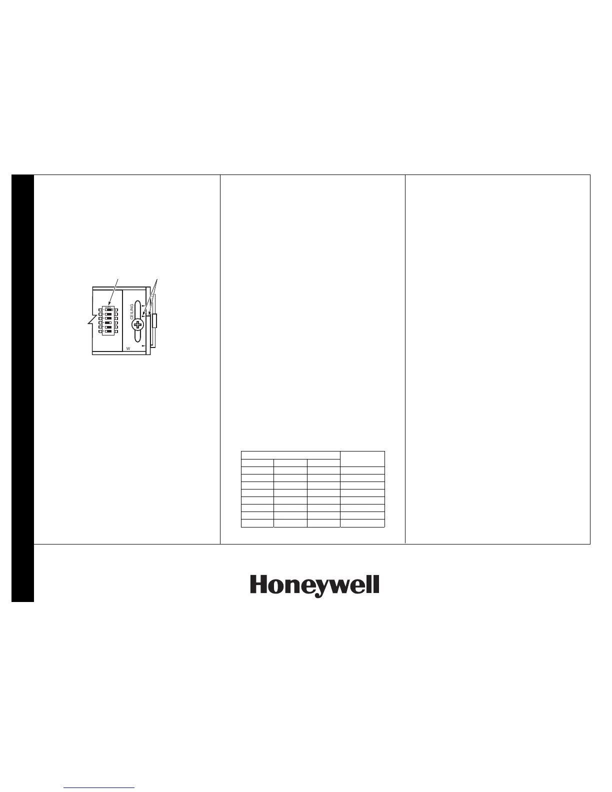
to be aligned with the ceiling or wall arrows. The
"L" designates long range and the "S" designates
short range.
NOTE: Either long or short range must be
selected. Attempting to select a "mid" range will
result in undesirable operation. A mid range setting
will not result in a mid range operation. It will only
provide a long range with attenuated short range
detection
.
3. Tighten the rotation locking screw.
310-003-V0
ALIGN
ARROWS
DIP
SWITCH
ON
654321
CEILING
WALL
S
L
S
L
7. Shutter Adjustment
The IS-310 contains shutters behind the PIR cover.
These shutters are used to adjust the field width. This
may be necessary when the unit is installed where it
may be tripped by non-exiting foot traffic or other
erroneous sources at either or both edges of the
detection area.
1. To adjust the shutters, remove the lens cover from
the PIR.
2. Push the forward edge of the shutter(s) toward the
middle of the opening until the area(s) to be
blocked are outside the line-of-sight of the PIR.
When making the shutter adjustment, each shutter
position has a detent and each detent masks off an
entire detection zone. There are eight zones total
and each shutter has the ability to mask off 7 of the
8 zones. If the shutter is located between detents,
the result will be an attenuation of a zone that is
intended to be masked or attenuation of a
detection zone resulting in improper operation.
3. Replace the lens cover.
8. DIP Switch Settings
The IS-310 DIP switch contains 6 switches for selecting
operating options. The functions of these switches are
as follows:
Switch 1 – Sensor Mode (Sensitivity) Selector:
OFF is
the Request-to-Exit mode. ON is the Security Sensor
mode. In the security sensor mode, the sensor is
more immune to false alarms, but the extra time
required to perform signal qualifications may make
the unit unsuitable for most RTE applications. The
unit is shipped in the Request-to-Exit mode.
Switch 2 – LED Disable:
This switch must be off to
allow the LED to function. The unit is shipped with the
LED enabled (switch OFF).
Switch 3 – Relay Timer Mode:
This switch selects the
relay timer re-trigger or fixed modes.
With this switch OFF, the re-trigger mode is selected.
In the re-trigger mode, the relay timer is restarted with
the time programmed (with switches 4, 5, and 6)
whenever motion is detected. The relay will only de-
activate when the time programmed expires without
additional motion detected during the active period.
With this switch ON, the fixed mode is selected and
the relay will deactivate at the expiration of the relay
time programmed (with switches 4, 5, and 6) and
additional motion detection during the active period
has no effect. The unit is shipped with this switch
OFF (re-trigger mode).
Switches 4, 5, and 6 – Relay Timer Setting:
These
switches control the relay timing: To set the relay
timing, refer to the following table:
Switch
4 5 6
Relay Time
(Seconds)
OFF OFF OFF 0.5
OFF OFF ON 1
OFF ON OFF 2
OFF ON ON 4
ON OFF OFF 8
ON OFF ON 16
ON ON OFF 32
ON ON ON 64
9. Walk Testing
Walk into the motion detection field. Two to four normal
steps into the field should make the LED light.
NOTE: The IS-310 has a warm-up period of approxi-
mately 2 minutes.
Each time the LED goes on, wait for it to go off. Then
wait 12 seconds before continuing the walk-test. When
there is no motion in the detection field, the LED should
be off.
IMPORTANT: The IS-310 should be tested at least
once a year.
10. Specifications
Range:
Long: 8.4’ x 15.8’ (Adjustable)
2.6m x 4.8m (Adjustable)
Short: 2’ x 5.5’ (Adjustable)
0.5m x 1.7m (Adjustable)
Relay (Dual):
Form C
Contact rating; 1A max. at 30
VDC max.
Power Requirements:
12 to 28 VDC or VAC
3V peak-to-peak @ 12.5V
<50 mA current consumption
Operating Temperature:
32° to 122°F (0° to 50°C)
Relative Humidity:
<95% non-condensing
RFI Immunity:
30 V/m, 1 MHz – 1000 MHz
White Light Immunity:
2000 Lux
Size:
7” x 2” x 2”
17.8cm x 5.1cm x 5.1cm
Part Numbers:
IS-310WH – White Housing
IS-310BL – Black Housing
Accessories:
IS-310WHTP – Single gang
trim plate, White
IS-310BLTP – Single gang
trim plate, Black
11. Regulatory Notices
The IS-310 fully complies with the following regulations:
• FCC Part 15
• UL 294 – Access Control System Units
• C22.2 No. 205-M1983 – Signal Equipment
• CE
©
2003 Honeywell International Inc.
All rights reserved.
IntelliSense is a registered trademark of Honeywell International Inc. - All
other brands mentioned are trademarks or registered trademarks of their
respective owners. Specifications subject to change without prior notice.
ÊK0923V2OŠ
K0923V2 5/03 Rev. B
 Loading...