- 3 -
1
Return the DT-600 to IntelliSense for repair.
Send the sensor in for repair.
1
Send the sensor in for repair.
1
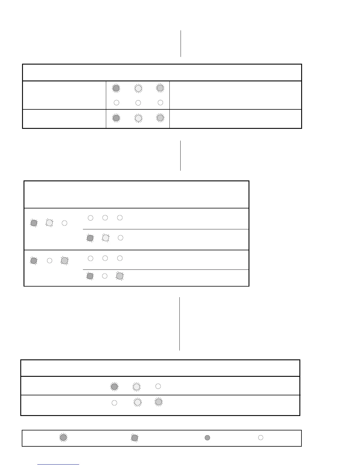
Microwave Pulse Self-Test
Temperature Compensation
Self-Test
ALARM MW PIR
TEST DESCRIPTION (Red) (Yellow) (Green) ACTION
Table 3
Trouble Output
Troubleshooting
Matrix
ALARM MW PIR
TEST DESCRIPTION (Red) (Yellow) (Green) ACTION
DT-600 sensors automatically perform a series of self-tests in the
following instances: when the sensor is powered up, when the tests
are installer initiated, upon command input, and periodically during
normal operation as on-going self-tests. When a self-test error
occurs, all three LEDs flash (if enabled) and the trouble output
becomes active until the failure is cleared. The following chart
describes how the diagnostic LEDs appear during self-tests, and
what action needs to be taken for each type of display.
Table 2 INFORMER
Troubleshooting Matrix
NOTE: If you enter the detection
pattern and the LEDs go off, you
can retrieve the LED pattern to
pinpoint the problem. Refer to the
Trouble Memory section below.
Power Up Self-Test (1 minute)
On Line - All Self-Tests Passed,
Ready for Walk-Test
1
Return the DT-600 to IntelliSense for repair.
Table 1
Self-Test
Troubleshooting
Matrix
The troubleshooting matrix below describes two trouble alerts
which are reported by the INFORMER circuit. To use this trouble-
shooting matrix:
1) Find the trouble alert that describes the condition of the walk-
test LEDs (with no motion in the area).
2) Walk-test the sensor, carefully watching the reaction of the
diagnostic LEDs.
3) Refer to the Possible Causes column of the matrix for an
explanation of the way in which the diagnostic LEDs reacted
to the walk-test.
Condition of LEDs
with No Motion
ALARM
(Red)
MW
(Yellow)
PIR
(Green)
ALARM
(Red)
MW
(Yellow)
PIR
(Green)
Reaction of LEDs
to Walk-Test
RATIO
IMBALANCE
MW environmental problem
MW unstable
MW range too long
PIR was blocked
PIR environmental problem
PIR unstable
MW range too short
RATIO
IMBALANCE
Type of
Problem
Possible
Causes
PIR range too short
PIR aimed wrong
PIR not reporting
MW range too short
MW not reporting
RATIO
IMBALANCE
RATIO
IMBALANCE
(Pattern disappears)
(Pattern disappears)
No action required.
Sensor is working properly.
TROUBLESHOOTING THE DT-600 SERIES SENSORS
Send the sensor in for repair.
1
On-going Self-Test
When the DT-600 signals a trouble output, the LEDs display a
failure pattern all three LEDs flash at the same rate.
You can recover the individual pattern to determine what trouble
occurred. To recover the LED pattern, remove the front housing
from the sensor. Use a screwdriver to connect the two (self-test)
pins at the left-hand side of the PCB (see Figure 3) and cause a
momentary short. The trouble LED pattern will reappear.
TROUBLE MEMORY
Connect the pins with the screwdriver again to clear the LED
pattern.
NOTE: The Trouble Memory only stores a single event (the last
event to occur) in memory. Once the LED pattern is cleared, the
memory is erased, and the self-test restarts.
The matrix below shows the individual patterns and the appro-
priate action.
LED Legend:
= LED is Flashing Fast = LED is OFF
= LED is Flashing Slow = LED is ON
 Loading...