JADE™ ECONOMIZER MODULE
63-2700—05 6
Sylk Bus Sensor Wiring
Use Fig. 6 and Table 3 to locate the wiring terminals for each
Sylk Bus sensor.
Use Fig. 6 and Table 4 to set the DIP switches for the desired
use of the sensor.
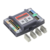
Fig. 6. Sylk Bus sensor DIP switches.
NOTE: When using the Sylkbus sensors there will be a
slight delay while the Jade controller and the sen-
sor communicate. Analog sensors do not commu-
nicate on the Sylkbus and output a 20k ohm
signal to the Jade controller so the response time
is instantaneous.
Actuator Wiring Options:
1. The JADE economizer controller can only have one (1)
communicating actuator connected to it.
2. Up to four (4) non-communicating and two (2) 2-position
actuators (1 each on EXH1 and AUX1 O)
3. One (1) communicating and up to four (4) non-communi-
cating and two (2) 2-position actuators (1 each on EXH1
and AUX1 O). When using a 2-position actuator on the
AUX1 O, the AUX1 O must be programmed for Exh2 and
the % open is the % open of the outdoor damper when
the 2-pos actuator opens. Connect 24 V to Exh1 and/or
AUX1 O and ground to the Jade "C" terminal.
Table 3. SYLK Bus Sensor Wiring Terminations.
Terminal
Type DescriptionNbr Label
1 S-BUS SYLK
Bus
Sylk Bus Communications
(Sensor Bus) polarity insensitive
2 S-BUS SYLK
Bus
Sylk Bus Communications
(Sensor Bus) polarity insensitive
Table 4. SYLK Bus Sensor DIP Switch Settings.
Use
DIP Switch Positions for Switches 1, 2, & 3
123
DA
a
a
DA = Discharge Air
OFF ON OFF
RA
b
b
RA = Return Air
ON OFF OFF
OA
c
c
OA = Outdoor Air
OFF OFF OFF
DIP
SWITCH
LABEL
M32271B
SYLK BUS
TERMINALS
(1 AND 2)
DIP
SWITCHES
(3)
SYLK BUS
2 PIN SIDE
CONNECTOR
 Loading...