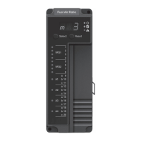
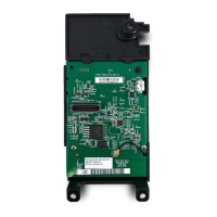
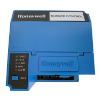
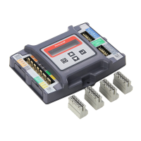
JADE™ ECONOMIZER MODULE
25 63-2700—11
ALARMS(#)
CONTINUE
D
SYS ALARM n/a n/a When AUX1-O is set to SYS and there is any alarm (e.g., failed sensors,
etc.), the AUX1-O terminal has 24 Vac out.
ACT UNDER V n/a n/a Voltage received by Actuator is above expected range
ACT OVER V n/a n/a Voltage received by Actuator is below expected range
ACT STALLED n/a n/a Actuator stopped before achieving commanded position
FEATURES ADJUSTABLE ONLY BY USE OF THE W7220 PC MOD TOOL
ACT STALL ALARM
SUPPRESSION
Disabled Enabled or
Disabled
If enabled this feature allows the operator to suppress the stall alarm in
a specific range of the actuator stroke.
SELECT TYPE OF
CONTROLLER
W7220 W7220,
W7218 or
Pre-
programmed
special
The operator can configure a program for a customer or job and save
the program in the file. Found on the configuration page of the Trade
version
ACTUATOR SLIPPAGE
ALARM
Enabled Enabled or
Disabled
Alarms if the actuator becomes disconnected from the damper or is
slipping on the shaft.
If Enabled, the Jade system will complete a system air temperature
check.
If there is the expected change in system air temperature, then Jade
assumes the actuator is connected to the damper.
If the expected system air temperature changes do not occur, then an
actuator slippage alarm is displayed on the Jade LCD. Found on the
configuration page of the Trade version.
ACTUATOR SLIPPAGE
ALARM SENSITIVITY
Low Low,
Standard or
High
Sensitivity can be set to HIGH, STANDARD or LOW. High means the
system will check 5 times for the damper to move before displaying the
alarm. Standard is 10 times before the alarm is displayed. Low is 20
times before the alarm is displayed. Found on the economizer page of
the Trade version.
LOCATION OF
ECONOMIZER
CONTROL SENSOR
Before the
cooling coil
Before coil or
AUTO
The operator can choose if the economizer control sensor (normally
referred to as the Mixed air sensor) is placed in the mixed air (before
the coil) or Auto in the case the sensor is placed after the cooling coil.
Found on the configuration page of the Trade version.
DAMPER AIA
THRESHOLD
15 degrees 5 to 40
degrees
Damper threshold feature (Adaptive Integral Action) is the difference
in the mixed air temperature reported by the MAT sensor and the MAT
setpoint. Lower (2 degrees) transfer rate between the actual MAT
sensor reading and the MAT setpoint normally means the damper is
closing and opening faster. Larger transfer rate (up to 20 degrees)
between the sensor reading and the setpoint normally means the
damper is opening and closing slower. Used in applications where
there is a large MA space or there is a long duct between the OA and
the MA causing a delay. Found on the economizer page of the Trade
version.
a
Table 5 illustrates the complete hierarchy. Your menu parameters may be different depending on your configuration.
For example if you do not have a DCV (CO
2
) sensor, then none of the DCV parameters appear.
b
When values are displayed, pressing and holding the or button causes the display to automatically increment.
c
n/a = not applicable
d
ERV Operation: When in Cooling mode AND the conditions are NOT OK for economizing - the ERV terminal will be
energized. In the Heating mode the ERV terminal will be energized when the OA is below the ERV OAT setpoint in the
setpoint menu.
e
When used with Honeywell communicating actuator the damper out is reported in XX.X% open versus XX.X Vdc.
f
After 10 minutes without a command or mode change, the controller will change to normal operation.
g
Default for AUX2 IN changed from SD to W1 with 1.15 firmware (June 2018).
h
Default for FAN SPEED changed from 1-speed to 2-speed with 1.15 firmware (June 2018).
Table 5. Menu Structure
a
. (Continued)
Menu Parameter
Parameter
Default
Value
Parameter
Range and
Increment
b
Notes
 Loading...
