MU1H-1417GE23 R1114 10 Honeywell GmbH
GB
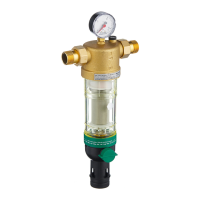
• A filter (e.g. F762) should be installed no more than 1
metre ahead in flow direction of the softening device to
protect the plant.
• The following is needed for operation in the close vicinity
of the device:
- a channel interface (at least DN50)
- separate mains connection (230 V / 50 Hz)
- Floor drain
8.2. Assembly instructions
1. Thoroughly flush pipework
2. Install softening device
• Note flow direction (indicated by arrow)
• Install without tension or bending stresses
3. Establish the connections to the softening device
4. Connect the sewerage tube to the discharge connection
(inner tube ø min. 13 mm, 1/2")
8.3. Complying with the limit for the sodium
concentration
When operating a softening device, the limit value for the
sodium concentration (acc. drinking water ordinance) of 200
mg/l may not be exceeded.
To reduce the water hardness by 1°dH, about 8mg/l sodium
needs to be added to the water. Additionally, the basic
sodium content* of the raw water needs to be taken into
account.
The maximum possible softening results from these values.
Example:
Result: the raw water hardness can be reduced
by 23.75 °dH.
* according to the water distribution company
9. Start-up
1. Put diluting device into bypass position
• close the two outer valves
• open the middle valve
2. Open shut-off valve on inlet
3. Put diluting device into operating position
• Slowly open the input valve completely
• Slowly open the output valve completely
• Close middle valve
4. Check that the water connections do not leak
5. Pour water (about 1 litre) into the salt supply container
6. Pour salt tablets into the salt supply container
7. Connect transformer to the device
• Remove cover to the salt container and hood
• Plug the cable shoes of the transformer into the
controller
8. Replace hood and cover, guide the cable out of the back
of the device
9. Connect the softening device to the mains via the trans-
former
10. Programming the softening device
9.1. Programming the softening device
9.1.1. Display and operating keys
To avoid irreplaceable damage to the softening device,
all welding and soldering work in the near vicinity should
be completed before the mounting.
Make sure the seal is fitted properly!
• The rinse water hose and the hose on the safety
overflow of the brine tank need to be laid out with a
decline towards the channel or fed into a pumping
station.
• The rinse water hose and the hose on the safety
overflow of the brine tank need to be mounted acc. to
DIN 1988 with at least 20 mm distance (free outflow)
to the highest possible drainage water level.
• The pumping station needs to be constructed for a
water amount of at least 2 m³/h or 35l/min and be
salt-water proof. The pumping station needs to have
a greater capacity accordingly if it is used for other
plants as well.
min. 20 mm
Basic sodium content* Na
act.
= 10 mg/l
Limit value acc. to TVO Na
max
= 200 mg/l
possible sodium dosage Na
dose
= Na
max
- Na
act
= 190 mg/l
possible softening 190 mg/l ÷ 8 mg/l = 23,75
Use only salt tablets acc. DIN 19604.
AKTUELLE ZEIT
REGENERATION MENU / OK
 Loading...