BCU 440 · Edition 01.17 23
Project planning information
6.7 Emergency stop
6.7. 1 In the event of fire or electric shock
If there is a risk of fire, electric shock or similar, inputs
L1 and N of the BCU should be disconnected from the
electrical power supply – this should be reflected in the
wiring on site.
6.7. 2 Triggered by the safety interlock (limits)
The safety interlock turns off the power to the input 1,
such as in the event of low air pressure or similar.
6.8 Fault signalling
The fault signalling contact opens, as soon as the mains
voltage fails.
6.9 Overload protection
To protect the unit against overload by frequent cycling,
only a specific number of start-up attempts can be car-
ried out by the BCU 440. On the BCU 440, a minimum
timing cycle of 2 minutes must be ensured on site.
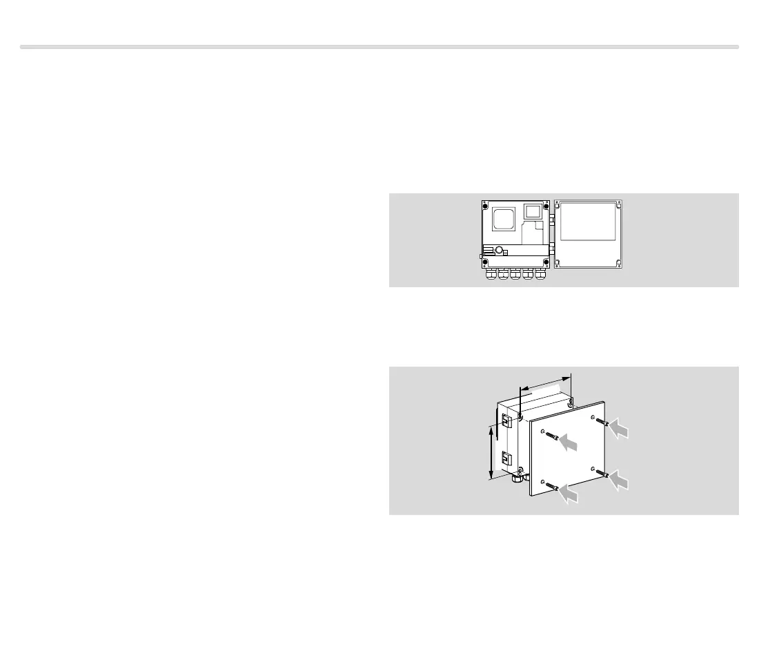
6.10 Installation
Recommended installation position: vertical (cable
glands pointing downwards).
When installing, ensure that there is sufficient space to
open the BCU.
From inside
Open BCU and screw on with four screws (Ø 4 mm, min.
length 15 mm).
From outside
163 mm
185 mm
7.28"
6.42"
Screw on the closed unit to the rear with 4 self-tapping
screws (enclosed).
Otherwise, mount with external securing bars or fasten-
ing set, see page 27 (Accessories).

 Loading...


