BCU 440 · Edition 01.17 32
88
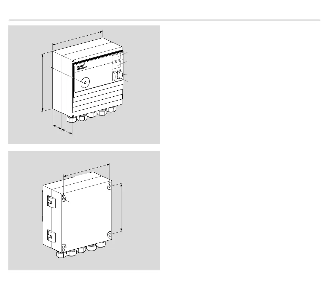
200 mm (7.87")
A
55
mm
B
C
D
E
200 mm (7.87")
50
mm
(1.97")
(2.17")
4,5 mm
0.177"
163 mm
6.42"
185 mm
7.28"
Technical data
9.2 Housing dimensions
Die-cast aluminium housing with plug-in terminal
blocks and plug-in M20 cable glands or (16-pin) plug
connector for input signals and optionally pre-assem-
bled cables for output signals.
9.3 Operating controls
A: Optical interface.
B: Labelling field for individual labelling of the system
components.
C: 2-digit 7-segment display.
D: Mains switch to isolate the BCU on two poles from
the mains.
E: Reset/Information button to reset the system after
a fault or to scan parameters on the display.
9.4 Installation
Recommended installation position: vertical (cable
glands pointing downwards).
Open the BCU and attach with four screws Ø 4 mm or
screw on the closed unit using the external securing bar,
see page 27 (Accessories).
Electrical connection via plug-in connection terminals
(2.5 mm²) and plug-in cable glands. The latter can be
removed in order to facilitate installation. When install-
ing, ensure that there is sufficient space to open the
BCU.

 Loading...


