GAS ELECTRO-MECHANICAL VALVES
E - m - 05/22 7 32M-95001—04
VALVE MODEL NUMBER DESCRIPTION
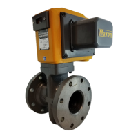
Every MAXON gas electro-mechanical valve can be accurately identified by the model number shown on the valve
nameplate. The example below shows a typical gas electro-mechanical valve model number, along with the available
choices for each item represented in the model number.
1
-18°C minimum ambient temperature limit
2
Motor timing not available on manual valves
3
2.5 second Motor timing only available on “S” Valves
Configured item number Valve body Actuator
Valve size
Flow capacity
Valve type
Normal position
Area
classification
Body
connection
Body seals &
bumper
material
Body material
Internal trim
package
Solenoid OR circuit
board voltage
Motor voltage
OR handle
side plate
Motor timing
(automatic
valves only)
Switch options
Enclosure rating
Instruction
language
300 C MA 1 1 - A A 1 1 - B B 2 0 A 0
Valve size
075 - DN 20 (3/4")
100 - DN 25 (1")
125 - DN 32 (1-1/4")
150 - DN 40 (1-1/2")
200 - DN 50 (2")
250 - DN 65 (2-1/2")
300 - DN 80 (3")
400 - DN 100 (4")
600 - DN 150 (6")
Flow capacity
S - Standard
C - CP body construction
H - High capacity
Valve reset type
MA - MAXON automatic
(motorized) valve
MM - MAXON manual valve
Normal position
1 - Normally closed shut-off valve
2 - Normally open vent valve
Area classification
1 - General purpose
2 - Non-incendive, Class I, II and
III Division 2
4 - Valve body only (400 & 600
high capacity valves only)
Body connection
A - ANSI (NPT) threaded
B - ANSI flanged (PN20)
C - ISO 7/1 threaded
D - DIN PN16 flanged
E - Socket welded nipple
F - Socket welded nipple w/Class
150 flange (ISO 7005 PN20)
H - EN1092-1 PN16 flanged
(ISO 7005-1 PN16)
Body seals & bumper material
A - Buna o-rings/Buna bumper
B - Viton o-rings/Buna bumper
C - Viton o-rings/Viton bumper
1
D -
Ethylene propylene o-rings
w/Ethylene propylene bumper
1
E -
Omniflex o-rings/Buna bumper
F -
Omniflex o-rings/Viton bumper
1
Body material
1 - Cast iron
2 - Carbon steel
5 - Stainless steel
6 - Low temp carbon steel
Internal trim package
1 - Trim package 1
2 - Trim package 2
4 - Trim package 2, oxy clean
1
Solenoid OR circuit board voltage
A - 115VAC 50 Hz
B - 115VAC 60 Hz
C - 230VAC 50 Hz
D - 230VAC 60 Hz
E - 208VAC 50 Hz
F - 24VDC
G - 120VDC
Motor voltage
A - 115VAC 50 Hz
B - 115VAC 60 Hz
C - 230VAC 50 Hz
D - 230VAC 60 Hz
E - 24VDC
Motor timing
2
1 - 2.5 Sec (3 Sec on 50 Hz)
3
2 - 6 Sec (7 Sec on 50 Hz)
3 - 12 Sec (14 Sec on 50 Hz)
* - N/A with manual
valves
OR
Handle side plate
A - Standard handle
Switch options
Automatic valves
0 - VOS1/none
1 - VOS1/VCS1
2 - VOS2/VCS2
3 - VOS2/VCS1
4 - VOS1HC/VCS1HC
Manual valves
0 - None
1 - VOS1/VCS1
2 - VOS2/VCS2
3 - VOS2/VCS1
Enclosure rating
A - NEMA 4
B - NEMA 4X
Instruction language
0 - English
 Loading...