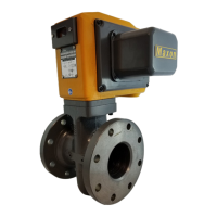
GAS ELECTRO-MECHANICAL VALVES
32M-95001—04 4 E - m - 05/22
INSTALLATION
1. A gas filter or strainer of 40 mesh (0.6 mm) or
smaller is recommended in the fuel gas piping to
protect the downstream safety shut-off valves.
2.
Properly support and pipe the valve in the direction of
the flow arrow on the valve body. Valve seats are direc-
tional. Sealing will be maintained at full rated pres-
sures in one direction only. Sealing will be provided in
reverse flow only at reduced pressures.
3.
Mount valve so that open/shut window indicator will
be visible to your operating personnel. The open/shut
window indicator should never face downward. The
valve side plates should be located in a vertical plane
for best performance. Valves are usually installed in
horizontal piping; however, other orientations are
acceptable, subject to the above limitations. The top
assemblies of all MAXON valves are field rotatable to
allow installations involving conflicts with these
mounting restrictions.
4.
Wire the valve in accordance with all applicable local
and national codes and standards. In U.S. and Can-
ada, wiring must conform to the NEC ANSI/NFPA 70
and/or CSA C22.1, Part 1.
• Supply voltages must agree with valve’s
nameplate voltage within -15%/+10% for proper
operation. For electrical wiring schematic, see
instructions or sample affixed inside valve
terminal block cover.
• Grounding is achieved with a grounding screw,
which is located in the top assembly.
• Customer connections are provided via terminal
blocks located in the top assembly.
• Main power wiring (120 VAC or 240 VAC) must be
segregated from lower voltage 24 VDC signal
wiring, when both are required.
• To eliminate any potential for gas to enter the
electrical wiring system, install a conduit seal
fitting at the actuator conduit hub.
5.
Maintain integrity of the electro-mechanical actuator
enclosures by using the appropriate electrical connec-
tors for the (2) 3/4” NPT conduit threaded connec-
tions. The electrical enclosure is NEMA 4 rated with an
option for NEMA 4X.
6.
All access cover plate screws should be tightened
using a torque wrench in an alternate cross-corner
tightening pattern to the values shown in “Table 1 -
Torque specifications” on page 3.
7.
Verify proper installation and operation by electrically
actuating the valve for 10-15 cycles prior to the first
introduction of gas.
8.
WARNING - Explosion hazard
• Do not connect or disconnect this equipment
unless power has been removed or the area is
known to be non-hazardous.
• Substitution of components may impair
suitability for Class I, Division 2 (applies to
MM12, MA12, MM22 and MA22 valves only).
9.
This equipment is suitable for installation in Class I,
Division 2 Groups B, C, D, and Class II Groups F and G,
and Class III hazardous locations or non-hazardous
locations (applies to MM12, MA12, MM22 and MA22
valves only).
10.
Never test gas valves, or the pipeline they are in, with
liquids. The design of the body prevents removal of the
liquid after testing, which can cause erratic function or
failure.
Auxiliary features
• Non-adjustable proof of closure switch(es) with
valve seal over travel interlock
• Auxiliary switch for indication of full travel (open for
normally-closed valves, closed for normally-open
valves)
Operating environment
• Actuators rated for NEMA 4 or optional NEMA 4X
• Ambient and fluid temperature range of -28°C to
60°C for S and C Model constructions
• Ambient and fluid temperature range of -28°C to
52°C for H Model constructions
• All valves for oxygen service or using Ethylene Pro-
pylene body seals are limited to a minimum ambient
and fluid temperature of -18°C
 Loading...