GAS ELECTRO-MECHANICAL VALVES
E - m - 05/22 9 32M-95001—04
Wand position (for normally-closed valves)
Mounting brackets
Reference mounting bracket A Reference mounting bracket B Switches mount on support stand
Fig. 1
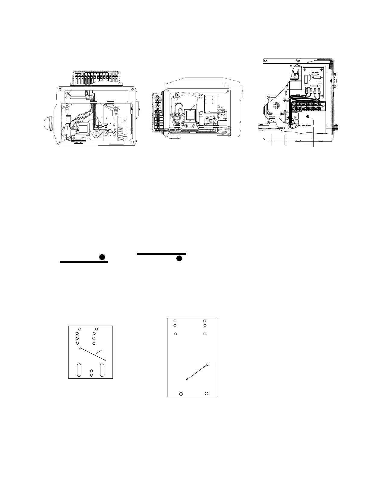
Manual reset actuator
DN20 - DN80 (3/4” - 3”) S Models
Fig. 2
Automatic reset actuator
DN65 C - DN100 C Models & DN150
(2-1/2” C - 4” C Models and 6”) S
Model
Fig. 3
Automatic reset actuator
DN100 & DN150 (4” & 6”) H Models
NCCOM
#1 BLACK TO
#3 BLACK TO
BLACK TO MOTOR
TERMINAL #1
TERMINAL #3
NO
1
2
12 11 10 9 8 7 6 5 4 3 2 1
TO CLUTCH
VOS switch wand should be
actuated from above
VCS switch wand should be
actuated from below
Mounting bracket A Mounting bracket B
VCS switch mounts
on back of bracket
Bracket
Mounting
Slots
2”-6”
1-1/2”
1-1/4”
3/4”, 1”
Drive
pins
VOS switch
on front
3”, 4”, 6” (-2)
3”, 4”, 6” (-2)
2-1/2” (-2)
2-1/2” (-1)
VCS switch
on back
Bracket
mounting
holes
VOS switch
on front
 Loading...