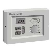
R7426D UNIVERSAL INPUT CONTROLLER
EN1B-0204GE51 R0403 8
Start Point Ystart (P.15)
The start point setting determines the relationship between
the midrange shift of the output Y1 and the corresponded
calculated control point.
It is calibrated in %, e.g. r.h., and is the change (plus or
minus) from the control point.
In humidification and dehumidification control the start point
has to be shifted by minus 50% of the proportional band Xp1.
Example:
• Set YCTRF to 1, reverse control behavior
• Set Xp1 at 6%
• Set start Ystart at minus 3%
With these settings, the humidifier valve will be fully closed, if
the actual humidity value is equal to the calculated control
point CTRP1 (zero deviation) and fully open at 6% r.h. below
CTRP1. At 6% r.h. above CTRP1, the controller provides an
output signal of plus 1200mV (100%) to fully open the cooling
valve by the plant temperature controller for dehumidification.
In P+I+D and P+I control the start point has to be set to the
same value as for P control.
Compensation Changeover Point W
comp
(P.03)
The control parameter W
comp
defines the start point of
summer or winter compensation. Above the compensation
changeover point (W
comp
) summer compensation and below
W
comp
winter compensation is performed.
Summer / Winter Compensation Authority
Su / Wi (P.04 / P.05)
These authority settings determine the reset effect (T
Comp
) of
the compensation sensor (T3) on the main setpoint W1 in
percentages.
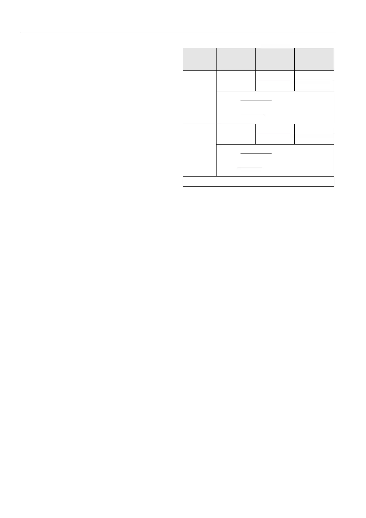
To calculate winter and summer authority for e.g. humidity
control, the throttling range has to be considered in
proportional only control according to Table 7.
Control
Schedule
Room
Humidity
(X1)
Outdoor Air
Temp.
(T3/T
comp
)
Throttling
Range
(X
P
)
50%rh 20°C 5%rh
40%rh -15°C 5%rh
Winter
(neg.
compensati
on)
Aut Wi = =⋅
∆
+∆
100%
AirOutside t
XX1
p
-14%100%
35
5+50)-(40
=≈⋅
50%rh 20°C 5%rh
60%rh 35°C 5%rh
Summer
(pos.
compensati
on)
Aut Su = =⋅
∆
−∆
100%
AirOutside t
XX1
p
33%100%
15
5- 50)-(60
+=≈⋅
Compensation change-over at +20 °C outdoor air temperature
Note: With P+I and P+I+D control X
p
= 0
Table 7. Calculation of Summer/Winter Compensation
Calibration of Sensors
X1CAL, X2CAL or T3CAL (P.17...P.19)
The controllers include a calibration setting and are factory
calibrated. In case of an offset as a result of long wiring
lengths the sensor inputs (X1, X2 and T3) can be adjusted
separately by the control parameters X1CAL, X2CAL and
T3CAL.
 Loading...