Do you have a question about the Honeywell BC-200 and is the answer not in the manual?
Details on isolating bells, warning systems, acknowledging, resetting, and isolating alarms.
Checklists for pre power-up and power up procedures for the BC-200.
Section for recording system faults, corrections, and test dates.
Overview of general device specifications and EMC compliance information.
Detailed electrical specifications for various power supply models.
Specifications for the Main Termination Board (FIM).
Specifications for Panel Expansion Relays (XR).
Specifications for LCM/LEM Addressable Loop Controller Modules.
Specifications for Network Control Modules (NCM-W, NCM-F, HS-NCM).
Specifications for the Fan Control Module.
Specifications for the AZM 8 Module.
Specifications for ACM-16AT, ACM-32A, SCS-8, and LDM-R32 Annunciators.
Specifications for the LCD80 Display Interface.
List of compatible Sealed Lead Acid (SLA) and Wet Lead Acid batteries.
Details on the BC-200 base system capabilities.
Information on available expansion Printed Circuit Boards (PCBs).
Details on analog addressable loop configurations.
List of supported annunciator types and their features.
Overview of available field modules and their capabilities.
Information on LCD80 Display Interfaces.
Description of the front panel LCD screen, hard and soft buttons.
Methods for selecting screen items and scrolling through lists.
Details on entering information, system counters, and point formats.
Explanation of how annunciators are addressed on the distributed ring.
Overview of the Service Menu structure and base level access.
Accessing various information lists within the Service Menu.
Viewing and managing alarm, fault, isolated, active, and pre-alarm events.
Accessing lists for zones, AZFs, digital outputs, and digital inputs.
Viewing lists for virtual points, network points, and communication rings.
Viewing lists for analog addressable loops, detectors, and modules.
Functionality for isolating or de-isolating system points.
Isolating zones, AZFs, Douts, Dins, and Virtual points.
Isolating analog detectors, modules, and ranges.
Performing group isolates and managing network isolates.
Options for configuring system points and modules.
Configuration of zones, AZFs, DOUTs, DINs, Virtual, and Network points.
Configuration settings for analog addressable points.
Procedure for adding or removing modules from the system.
Functions related to analog device management.
Managing analog devices: lists, status, changes, removal, loops, and settings.
Reference list of analog device fault codes and their meanings.
Performing functional tests on system components.
Tests for AZF and Analog devices, including alarm and fault tests.
Testing digital outputs and battery capacity.
Guidelines for performing walk tests on system devices.
Configuration of system-wide global parameters.
Setting global system parameters, date, time, and day/night schedules.
Managing system passwords and site contact details.
Configuration for system printer port parameters.
Tools for system diagnostics and fault finding.
Displaying system statistics and performing basic tests.
Performing tests on modules and local Input/Output.
Operations for history erase, system restart, and de-isolation.
Configuration and information for network operations.
Discovering network nodes and displaying remote node status.
NCM switch functions, termination, and diagnostic LEDs.
Configuring network operational parameters.
Logging off the current user session.
Creating and managing control scripts and virtual points.
Available logic functions for script creation (OR, AND, NOT, RANGE, etc.).
Special functions for fault, isolate, pre-alarm, and S pre-operator.
Using ANY and TIM operators for conditional scripting.
Using the ‘S’ pre-operator to reference point states in scripts.
Understanding and using network points (Netpoints) in scripts.
Details on special net points like NP1000, NP900-NP999.
Functional descriptions for Alarm Verification Facility (AVF) and Timed AZF.
Description of BC-200 password access levels and their permissions.
Operating instructions for the LCD80 display interface.
Using the LCD80 in terminal mode for display and operation.
Using the LCD80 in annunciator mode for pre-programmed messages.
Guidelines for cabling RS-485, Addressable Loops, and Network circuits.
Requirements for RS-485 ring communication cabling.
Specifications for addressable loop cabling, including distance and wire types.
Requirements for network cabling, including wire and fiber optic circuits.
Details on detector initialization, pre-alarm, and sensitivity settings.
Processes for detector initialization and self-optimizing pre-alarm.
Nine sensitivity levels for alarm and pre-alarm detection.
Sensitivity settings and application guide for the Smart 4 detector.
Explanation of drift compensation and maintenance warning levels.
List of fault codes for analog devices and their possible causes.
Diagrams illustrating panel and module connections.
Diagrams for connecting components to the FIM.
Wiring diagrams for PS243/PS249 and NPS power supplies.
Specific connection details for RS485, 24VDC, and AZF inputs on the FIM.
Connecting relay outputs and panel expansion relays to the FIM.
Information on the CPU module, including port settings.
Details on the Loop Interface Module (LIM) and its address settings.
Connections and wiring styles for Analog LCM and LEM modules.
Description of different loop wiring styles (4, 6, and 7).
Procedures for analog loop installation checks and fault finding.
Overview of BC-200 networking capabilities and modules.
Details on the Network Interface Module (NIM).
NCM switch functions, terminations, and diagnostic LED indicators.
Information on modem, printer, and HLI interfaces.
Details on PC and FIP modem interfaces and their settings.
Specifications for the modem to FIP cable connection.
Using the printer port for interfacing and understanding output formats.
Formulas and tables for calculating battery requirements.
Calculations for quiescent current, alarm current, and power supply capacity.
List of field replaceable sub-assemblies and parts.
Wiring diagrams for field modules.
Connection diagram for the AZM-8 Field Module.
Connection diagram for the Fan Controller Module.
Diagrams and notes for annunciator connections.
RS485 communication and power connections for annunciators.
Details for ACM-16AT, ACM-32A, SCS-8, LDM-32, LDM-R32, and LCD80.
Diagrams for Panel Expansion Relays.
Details on various analog addressable devices.
Wiring for 501 Detector Base and LPB-W Sounder/Strobe base.
Wiring diagram for the B524IEFT-1 Isolator Base.
Diagrams for Isolation Modules (ISO-X).
Connection diagram for the FRM-1 Relay Module.
Connection diagram for the FCM-1 Control Module.
Connection diagram for the FZM-1 Zone Module.
Connection diagrams for Monitor Modules.
Connection diagram for the Mini Monitor Module.
Connection diagram for the 10 x Monitor Module.
Connection diagram for the 6 x Conventional Zone Interface Module.
Connection diagrams for 6 x Relay Module and 2 x Monitor & 2 x Relay.
Connection diagram for the 6 x Control Module.
Wiring diagram for Fan Controls.
Connection diagrams for NPS power supplies.
Wiring diagram for connecting NPS to IFS-714 board.
Wiring diagram for connecting NPS to IFS-724 board.
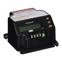
| Controller Type | Building Controller |
|---|---|
| Housing Material | Plastic |
| Supply Voltage | 24 VAC |
| Output Type | Relay |
| Operating Temperature | 0 to 50°C |