Specifications & Approvals
BC-200 Manual – P/N DOC-01-013 14
4
4
.
.
3
3
.
.
6
6
F
F
A
A
N
N
C
C
O
O
N
N
T
T
R
R
O
O
L
L
M
M
O
O
D
D
U
U
L
L
E
E
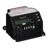
Supply Input IFS-700: 20 to 28Vdc
55mA max (no relays energised)
130mA max (all inputs and relays energised)
IFS-710: 15 to 28Vdc
55mA max (no relays energised)
130mA max (all inputs and relays energised)
Inputs 3 x Opto Isolated 4k7 EOL
Outputs 3 x ELV 1A relay contact outputs (Max 30 Vdc or 24 Vac)
Communications Link EIA485 on dual ports
Indications LED indications on: Inputs,
Outputs
RX/TX
Power
Fault
4
4
.
.
3
3
.
.
7
7
A
A
Z
Z
M
M
8
8
M
M
O
O
D
D
U
U
L
L
E
E
Supply Input IFS-701: 20 to 28V DC
90mA max (no relays energised)
155mA max (all relays energised)
IFS-711: 15 to 28V DC
80mA max (no relays energised)
125mA max (all relays energised)
238mA max (all AZF & relays energised)
43mA max (no relays energised, all AZF disabled)
Inputs 8 conventional alarm inputs
Monitoring – Open Circuit, Alarm, Fault
Outputs 4 x ELV 1A relay contact outputs (Max 30 VDC or 24 VAC)
Communications Link EIA485 on dual ports
Indications LED indications on: Outputs, RX/TX, Power,Fault
4
4
.
.
3
3
.
.
8
8
A
A
C
C
M
M
-
-
1
1
6
6
A
A
T
T
A
A
N
N
N
N
U
U
N
N
C
C
I
I
A
A
T
T
O
O
R
R
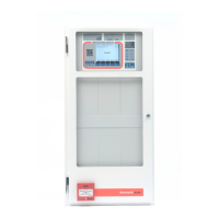
Supply Input 20V to 28Vdc
40mA standby
180mA alarm (All LED’s on)
Communications Link EIA485 multi-dropped
4
4
.
.
3
3
.
.
9
9
A
A
C
C
M
M
-
-
3
3
2
2
A
A
A
A
N
N
N
N
U
U
N
N
C
C
I
I
A
A
T
T
O
O
R
R
Supply Input 20V to 28Vdc
40mA standby
180mA alarm (All LED’s on)
Communications Link EIA485 multi-dropped
 Loading...