page 8 of 24 www.honeywellsafety.com
These are recommendations. If it is secured, that the cable will not
touch the steel structure, the maximum distance between the
intermediates can be used.
B6. At least the following components must be used when installing the
Söll Vi-Go system:
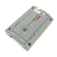
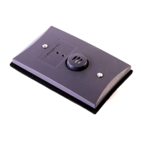
1. Cable tensioner
(2)
2. Cable 7 x 19 (8 mm / 10 mm / 3/8“)
(3)
B7. Installing the Söll Vi-Go system:
1. Fasten the steel Cable (3) at the upper attachment
point.
2.
Install the cable tensioner (2)
at
the lower attachment
point.
Fig. B2
A: Tensioning
element
B: Tension
reading
C: Rope attachment
point
D:
Lock
nuts
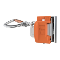
3. Hang the cable (3) at the cable attachment point (C) of the cable
tensioner
(2).
4. Turn the tensioning element (A) counter clockwise until the
tension reading (B)
is
between
the
minimum
and the
maximum
marking.
At 500 N the
cable
is
sufficiently
pre-tensioned.
5.
Secure
the
tensioning element
(A)
against twisting using
the
two
locking nuts
(D).
B8. Note
The cable
of the
Vi-Go
system must
be
pre-tensioned
to
ensure
the
correct functioning
of the shuttle. The required pre-tension is 500 N
(+/- 100
N).
 Loading...