43-TV-33-56 iss.4 GLO Aug 19 UK 8
Remove Alarm/Digital IO card
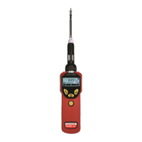
If the alarm card is being replaced, locate and remove the M3 x 8 earth screw from the bottom position of the unit,
(Minitrend and eZtrend = Slot G, Multitrend = Slot G, H and I) see Figure 13, 14 and 15.
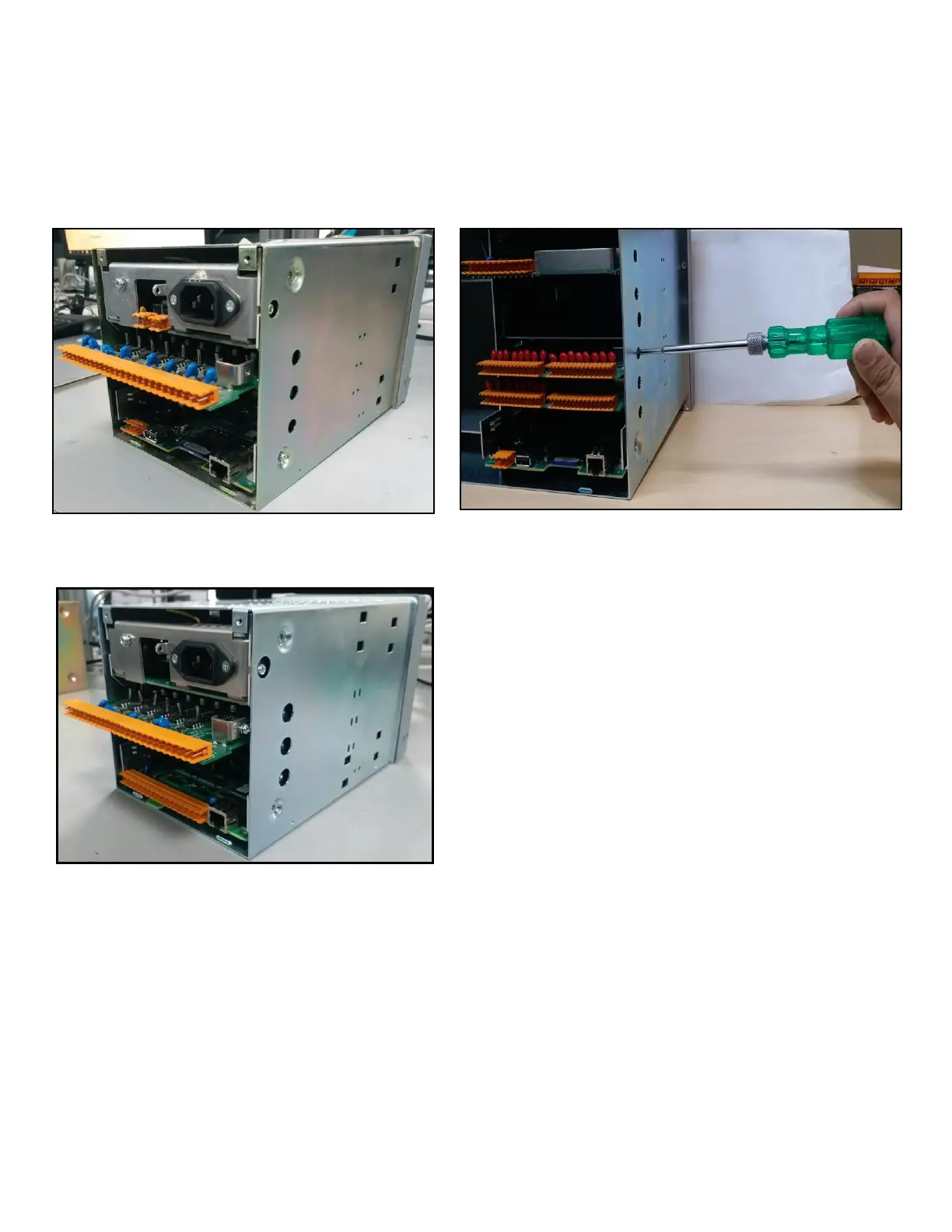
Grip the connector on the Alarm/Digital IO card and gently pull to release the card from its connection to the mother
board (expansion board on the eZtrend) at the front of the unit. Remove the card and retain both the screw and the
shake-proof washer.
Inserting an Alarm/Digital IO card
NOTE: To add an Alarm/Digital I/O board to the eZtrend recorder, the recorder must already have an Expansion board
fitted. If the Expansion board is fitted continue as described below, if an Expansion Board has to be fitted refer to
Instruction sheet 43-TV-33-81 “eZtrend Expansion Board”. Minitrend and Multitrend recorders will always have a Mother
Board already fitted.
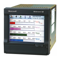
To replace or add an Alarm/Digital IO card, insert the new card in the correct slot position using the board guides in the
case. Slide the card carefully back into the case, until the fixing bracket on the left side of the card is in line with the
single fixing hole on the side of the case. Ensure the card is pushed fully home.
Replace/fit the M3 x 8 earth screws and shake-proof washers, on the side of the case, to secure the card.

 Loading...