Do you have a question about the Honeywell E-Mon Class 3200 and is the answer not in the manual?
Details the main power board and its connections for power input and current sensors.
Describes the display board, its connection to the main board, and its LCD display.
Details compliance with FCC rules for digital devices and potential radio frequency interference.
States compliance with BACnet MS/TP, IP protocol, and LonWorks TP/FT-10 protocol.
Provides warnings about electrostatic discharge and high voltages on terminal blocks.
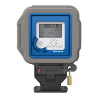
Details the physical mounting dimensions and installation guidelines for the meter enclosure.
Explains how to install the protective earth ground and connect main power to the board.
Details wire entry, MAINS wiring, neutral connection, earth ground, and external switch/fuse installation.
Covers connecting AC power wires, turning on power, and verifying voltage readings on display screens.
Describes how to verify correct phase sequence and voltage readings on the meter display.
Explains the installation and wiring of split-core and solid-core current sensors.
Details connecting current sensors to the main board and using diagnostics for proper installation.
Describes applying power to the meter after wiring and the function of status LEDs.
Provides wiring diagrams for 3-phase, 4-wire and single-phase, 3-wire installations.
Explains diagnostic messages related to missing phases or incorrect phase sequence.
Details diagnostic checks for reversed sensors, incorrect phase correspondence, and low power factor.
Explains the daisy-chain method for connecting meters via RS-485 terminals.
Details the use of DIP switches for enabling bias resistance on the RS-485 circuit.
Explains connecting a local computer to the RS-485 network using an RS-232 conversion key.
Describes connecting E-Mon Class 3200 meters to a PC via an RS-232 key for communication.
Details the components and steps for connecting the RS-232 key to a computer.
Covers connecting the AC adapter for the RS-232 key and its status indicators.
Explains connecting meters to the RS-232 key using RS-485 ports and the modular plug method.
Describes connecting the RS-485 network to a telephone line via the RS-232 key with modem.
Details connecting an external modem to the RS-232 key and configuring jumpers for modem mode.
Explains how to select the communication Baud rate using DIP switches on the meter circuit board.
States that BACnet MS/TP wiring is the same as Modbus and EZ7 wiring.
Explains connecting meters to a USB key via RS485 for PC communication and daisy-chaining.
Provides notes on using current sensor sets and multipliers for multiple load monitoring.
Provides warnings about using correct battery part numbers and handling precautions.
Details the procedure for replacing the lithium battery cell, including polarity and disposal.
Describes the initial screens displayed by the meter upon startup, showing firmware and configuration details.
Explains the seven normal mode display screens and how to 'lock' the scrolling display.
Details how to program the meter's display screens using the push button switches.
Provides step-by-step instructions for setting the date and time on the meter display.
Explains how to change the Device ID for EZ7 and ModBus configurations using the meter's buttons.
Details the procedure for resetting the recorded peak kW demand on the meter.
Describes how to lock the display scrolling on a specific screen for a set duration or indefinitely.
Explains the wiring for 3-wire high voltage circuits and the conversion process using CTs and sensors.
Details the calculation of the meter multiplier based on CT and PT ratios for high voltage applications.
| Category | Measuring Instruments |
|---|---|
| Accuracy | ±0.5% |
| Frequency Range | 50/60 Hz |
| Frequency | 50/60 Hz |
| Display Type | LCD |
| Operating Temperature | -20°C to 60°C |
| Input Voltage | 120-480V AC |
| Communication Protocol | Modbus RTU, BACnet MS/TP |
| Communication | Modbus, BACnet |
| Display | LCD |
| Enclosure | NEMA 12 |