E-MON CLASS 3200 METER
17 62-0397—02
6.4 Current Sensor Installation & Wiring
Once the AC voltages have been confirmed to be within acceptable limits, you are
ready to install the current sensors. TB2 is the input for Phase A, TB3 is the input
for Phase B and TB4 is the Phase C input. For the Single Phase option: use TB1
pos 5&6 are for the A Phase - TB1 pos 7&8 are for the B phase -factory installed
jumper wire on positions 9&10. Factory installed Jumper should not be removed.
The E-Mon Class 3200 meter is supplied with two types of 0-2V split or solid-core
current sensors (specified when ordered):
1. Split-core current sensor. This sensor opens so that it can be attached
around the circuit being monitored without interrupting power.
2. Solid-core current sensor. This sensor does not open and requires the mon-
itored conductor to be removed from the circuit to install the current sensor.
This type is only supplied when specified at time of order.
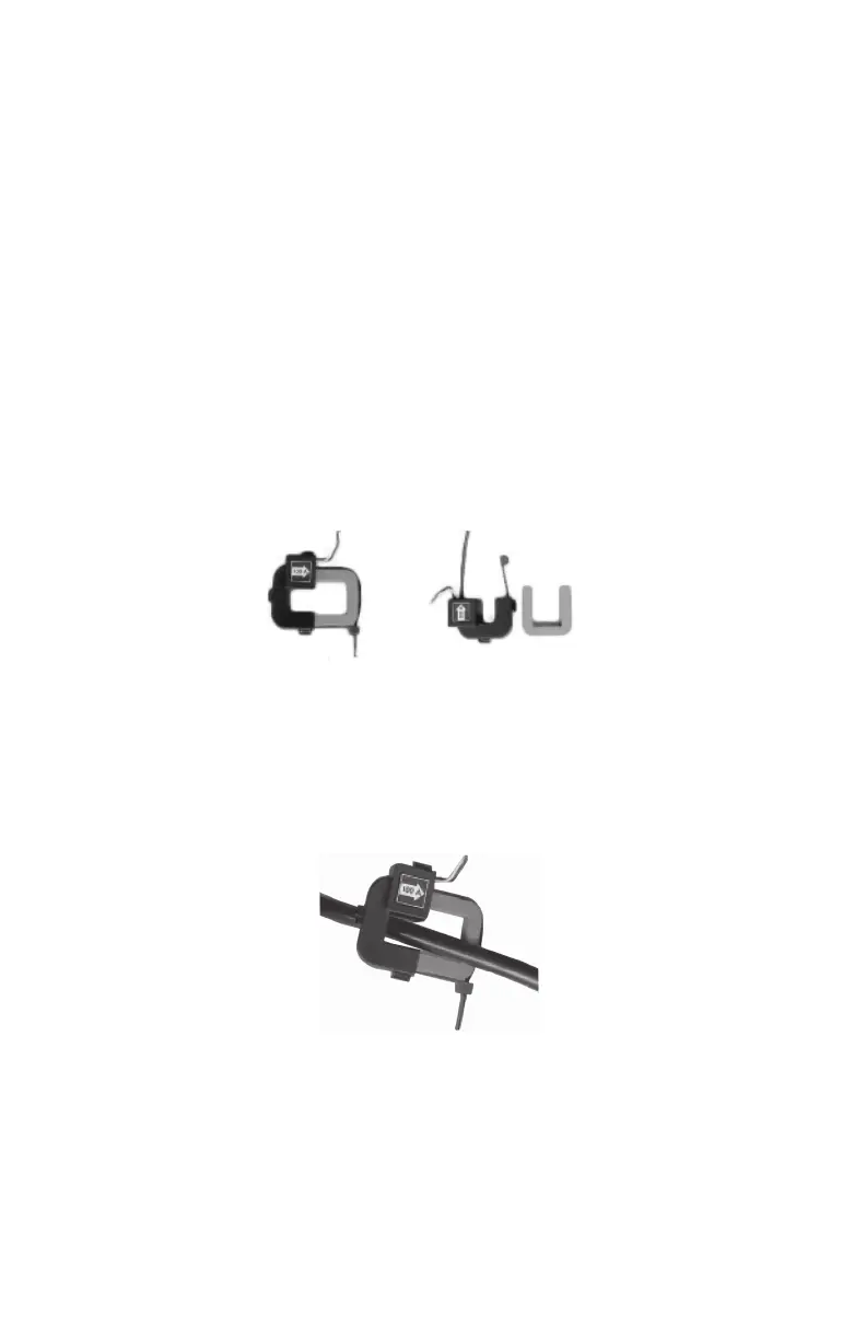
6.4.1 Installing the Split-Core Current Sensor Assembly
1. Each phase being monitored will require one two-piece current sensor
assembly. Open the two-piece current sensor assembly by releasing the
nylon clamp using a flathead screwdriver.
Fig. 7. Split Core Sensor.
2. Reassemble the current sensor assembly around the conductor(s) to be
monitored. Ensure the current sensor halves marked “Load” are both facing
the load side of the conductor. The colored arrow will be on the source side
of the conductor being monitored and MUST be pointed in a clockwise
direction around the conductor being monitored. Tighten the nylon clamp
to complete the assembly.
Fig. 8. Split Core Sensor.
IMPORTANT:
When looking from the source side of the conductor(s) being monitored,
you should see the arrow on the current sensor assembly. The arrow
should be pointing in a clockwise direction around the conductor(s) being
monitored. If the arrow is not positioned on the source side, inaccurate
readings will result.
M33213
LOAD
SOURCE
62-0397_C.fm Page 17 Wednesday, May 9, 2018 9:28 AM

 Loading...