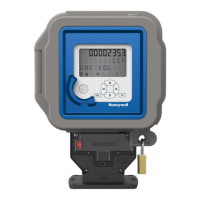
E-MON CLASS 3200 METER
Home and Building Technologies
In the U.S.:
Honeywell
715 Peachtree Street NE
Atlanta, GA 30308
customer.honeywell.com
® U.S. Registered Trademark
© 2018 Honeywell International Inc.
62-0397—02 M.S. Rev. 05-18
Printed in United States
This special high voltage meter installation shows the correct wiring procedure
for 4-wire high voltage circuits. In this application, the 3 element meter
connection is used on the secondary circuits of the user supplied high voltage
PTs and CTs.
The Honeywell meter used in this application is the model E32-12025HV kWh
meter.
Installation of these meters requires the use of three (3) current sensors mounted
on the secondaries of the high voltage Current Transformers. See the drawing
above for proper wiring. For correct operation, the meter must be installed
correctly.
This special high voltage meter installation utilizes high voltage PTs (Potential
Transformers) and CTs (Current Transformers) supplied by others. The Honeywell
meter is installed using the secondary outputs of these devices.
High voltage PTs reduce the primary voltage (4160v, 13200v, etc.) to a Secondary
output of 120v. This secondary is connected to the Honeywell E-Mon meter
voltage inputs as shown in the wiring diagram. High voltage CTs reduce the
primary current (amps) to a directly proportional 0~5 amp output. As an example,
a 0~400 amp primary becomes a 0~5 amp proportional signal from the
secondary output. This allows much smaller wiring to be utilized in the meter
hookup. The high voltage CT secondary is installed as a continuous “loop”, with a
single lead connected to both secondary terminals.
Honeywell E-Mon meters accept a 0~2 volt signal from their Current Sensors. To
convert the 0~5 amp signal, the Current Sensors are installed on the CT
secondary lead. A set of 25 amp sensors is used in this application. These sensors
have the high voltage CT secondary lead passed through them five (5) times by
looping the wire as shown in the drawing. This allows a direct conversion of the
CTs primary current to a directly proportional 0~2 volt signal, which is used by the
meter.
Since there is a signal ratio introduced by the high voltage CTs and PTs, it will be
necessary to multiply the number on the meter’s display for a correct reading. The
meter multiplier is calculated by using the CT ratio and the PT Ratio. [PTr x CTr /
Number of Secondary Lead Passes Through Sensor]. The Honeywell 25 amp HV
kWh meter with 5 wraps of the high voltage CT secondary will have its multiplier
calculated by the formula shown below.
EXAMPLE: CT = 400:5 = 80:1 (CTr = 80)
PT = 4200:120 = 35:1 (PTr = 35)
Wraps (Passes) = 5
METER MULTIPLIER = PTr x (CTr/Wraps)
35 x (80/5)
35 x (16) = 560
62-0397_C.fm Page 44 Wednesday, May 9, 2018 9:28 AM

 Loading...