ML6421, ML7421 NON-SPRING RETURN ELECTRIC LINEAR VALVE ACTUATORS
63-2515—4 4
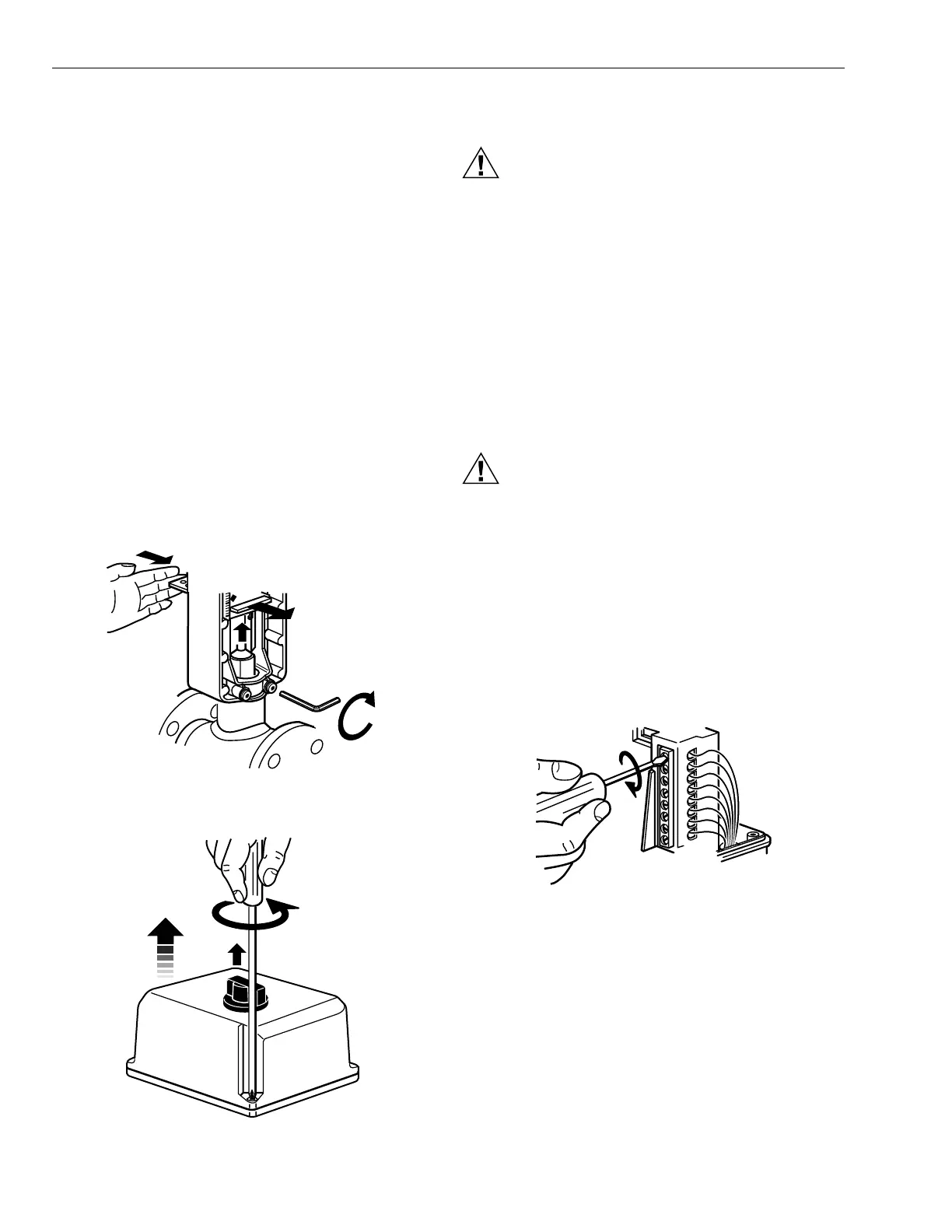
Mounting
1. Place the actuator on the valve with the U-bolt around
the valve collar. See Fig. 2.
IMPORTANT
When tightening the set screws, first tighten the right
set screw. See Fig. 2.
2. Place the U-bolt against the valve collar and secure the
actuator to the valve by turning each U-bolt nut clock-
wise.
NOTE: To assure even pressure on the collar, first
tighten the nuts finger-tight and then alternate
turning each U-bolt nut until both are snug.
3. Push aside the stem button retaining clip and hold. See
Fig. 2.
4. Lift the valve stem until the head of the valve stem
button is inside the large slot of the stem button
retaining clip on the actuator.
5. Release the stem button retaining clip to secure the
stem button. Check to make certain the stem button is
secured by the retaining clip.
6. Pull off the manual operation knob.
7. Remove the cover from the actuator using a Phillips or
crosspoint screwdriver. See Fig. 3.
Fig. 2. Attaching actuator to valve.
Fig. 3. Removing actuator cover.
Wiring
CAUTION
Electrical Shock or Equipment Damage Hazard.
Can shock individuals or short equipment
circuitry.
Disconnect power supply before installation.
IMPORTANT
1. All wiring must comply with local electrical codes,
ordinances and regulations.
2. Voltage and frequency of the transformer used with
the actuator must correspond with the characteristics
of the power supply and those of the actuator.
NOTE: See Fig. 5 through 8 for typical wiring hookups.
1. Feed power and control wires through the conduit
connector located on the bottom of the actuator case.
CAUTION
Equipment Damage Hazard.
Conduit connection or removal can break an
unsupported connector.
When removing or attaching conduit, use a wrench to
support the motor connector.
2. Using the appropriate wiring diagram (see Fig. 5 through
8), connect power and control wires to the actuator.
Make sure that all wiring is correct.
3. For the ML7421 only: Check selector plugs for proper
settings. See Signal Input Failure section for details.
4. When wiring is complete, replace the actuator cover
and control knob (see Fig. 9).
5. Apply power and control signals to the actuator.
Fig. 4. Connecting wiring to the actuator.
M
17431
TIGHTEN RIGHT
SET SCREW FIRST
M17432
M6630