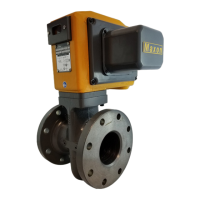
VRN PRESSURE INDEPENDENT CONTROL VALVES AND ACTUATORS
15 38-00032—01
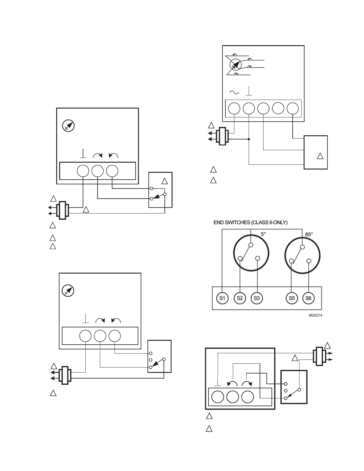
Electrical Installation
1. If necessary, remove actuator wiring cover.
2. Wire actuator using Figures 11 through 19 for the
application required.
3. Replace cover.
Wiring
VALVES WITH FAIL IN PLACE ACTUATORS
Fig. 11. MN6105 with On/Off Control.
Fig. 12. MN6105 with Floating Control.
Fig. 13. MN7505 with Modulating Control.
Fig. 14. Wiring for model with aux./end switches.
Fig. 15. MVN613 or MVN643 with Floating Control.
432
FLOATING ACTUATOR
24 VAC
1
1
POWER SUPPLY. PROVIDE DISCONNECT MEANS AND OVERLOAD
PROTECTION AS REQUIRED.
CONNECTION REQUIRED FOR SPST CONTROL.
24 VDC SUPPLY ACCEPTABLE FOR MVN643.
2
CONTROLLER
2
DIRECT
REVERSE
SERVICE/OFF
M34869
3
3
4
3
2
FLOATING ACTUATOR
24 VAC
Direct
Reverse
Service/Off
1
1
POWER SUPPLY. PROVIDE DISCONNECT MEANS
AND OVERLOAD PROTECTION AS REQUIRED.
FLOATING
CONTROLLER
M18946A
24 VAC
1
1
POWER SUPPLY. PROVIDE DISCONNECT MEANS
AND OVERLOAD PROTECTION AS REQUIRED.
PROPORTIONAL
CONTROLLER
+
–
FEEDBACK
1
325
PROPORTIONAL ACTUATOR
FEEDBACK
+
0(2)-10 VDC OF 0(4)-20 mA CONTROL SIGNAL ACCEPTABLE.
SET CONTROL SIGNAL DIP SWITCH TO “OFF” FOR VOLTAGE.
SET TO “ON” FOR CURRENT.
2
2
2 -10 Vdc
2 -10 Vdc
0 -10 Vdc
0 -10 Vdc
M18947B
4
FLOATING ACTUATOR
24 VAC
1
POWER SUPPLY. PROVIDE DISCONNECT MEANS AND OVERLOAD
PROTECTION AS REQUIRED.
USE CLASS II 24V TRANSFORMER FOR MVN643.
FLOATING
CONTROLLER
M33137C
2
3
4
1
BLACK
WHITE
BROWN
2
2
 Loading...