MS4120F; MS4620F; MS8120F; S2024-F; S20230-F FAST-ACTING, TWO-POSITION ACTUATORS
63-2584—10 6
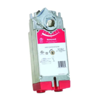
Manual Positioning
The actuator can be operated with no power present. Use this
feature during installation or to move and lock the damper or
valve shaft position when there is no power.
To operate the manual positioning:
1. If the power is on, turn it off.
2. Insert supplied hex wrench (key) as shown in Fig. 6.
3. Rotate key in the direction indicated on the cover.
4. Once the desired position is reached, hold the key to
prevent the spring return from moving the actuator.
NOTE: No detente for fire and smoke actuators. If key
is released, actuator will return to spring
closed position.
Fig. 6. Manual positioning.
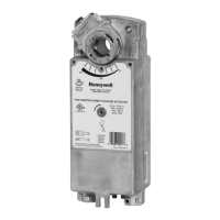
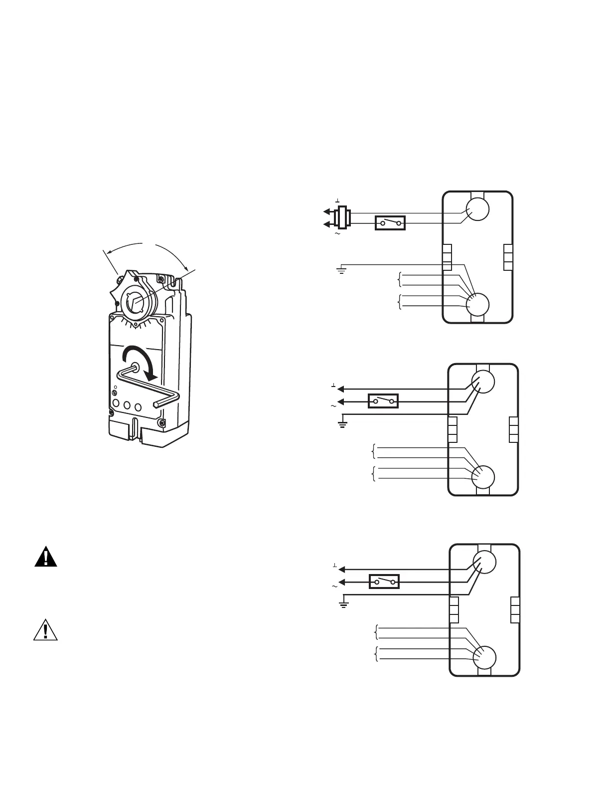
WIRING
See Fig. 7 through 11 for typical wiring diagrams.
Electrical Power Hazard.
Line voltage can cause death or serious injury and
short equipment circuitry.
Disconnect power supply before installation.
Electrical Shock or Equipment Damage Hazard.
Disconnect all power supplies before installation.
Motors with auxiliary switches can have more than one
disconnect.
IMPORTANT
1. All wiring must comply with local electrical codes,
ordinances and regulations.
2. Voltage and frequency of transformer used with
MS8120F,S and S2024-F must correspond with the
characteristics of power supply and actuator.
NOTE: The conduit fittings are designed for use with 3/
8 in. reduced-wall steel or aluminum flexible con-
duit.
Fig. 7. Typical 24 Vac wiring (MS Series).
Fig. 8. Typical 120 Vac wiring (MS Series).
Fig. 9. Typical 230 Vac wiring (MS Series).
M20053A
24 VAC
BLACK
RED
GREEN
MS8120F
L1
( )
L2
( )
YELLOW
YELLOW
BLUE
7° AUXILIARY
SWITCH
85° AUXILIARY
SWITCH
BLUE
M20056A
WHITE
BLACK
GREEN
MS4120F
L1
( )
L2
( )
YELLOW
YELLOW
BLUE
BLUE
7° AUXILIARY
SWITCH
85° AUXILIARY
SWITCH
120 VAC
M20057A
BLUE
BROWN
GREEN
230 VAC
MS4620F
L1
( )
L2
( )
YELLOW
YELLOW
BLUE
BLUE
7° AUXILIARY
SWITCH
85° AUXILIARY
SWITCH
 Loading...