3 NM SERIES SPRING RETURN DIRECT COUPLED ACTUATORS
31-00141M—06 8
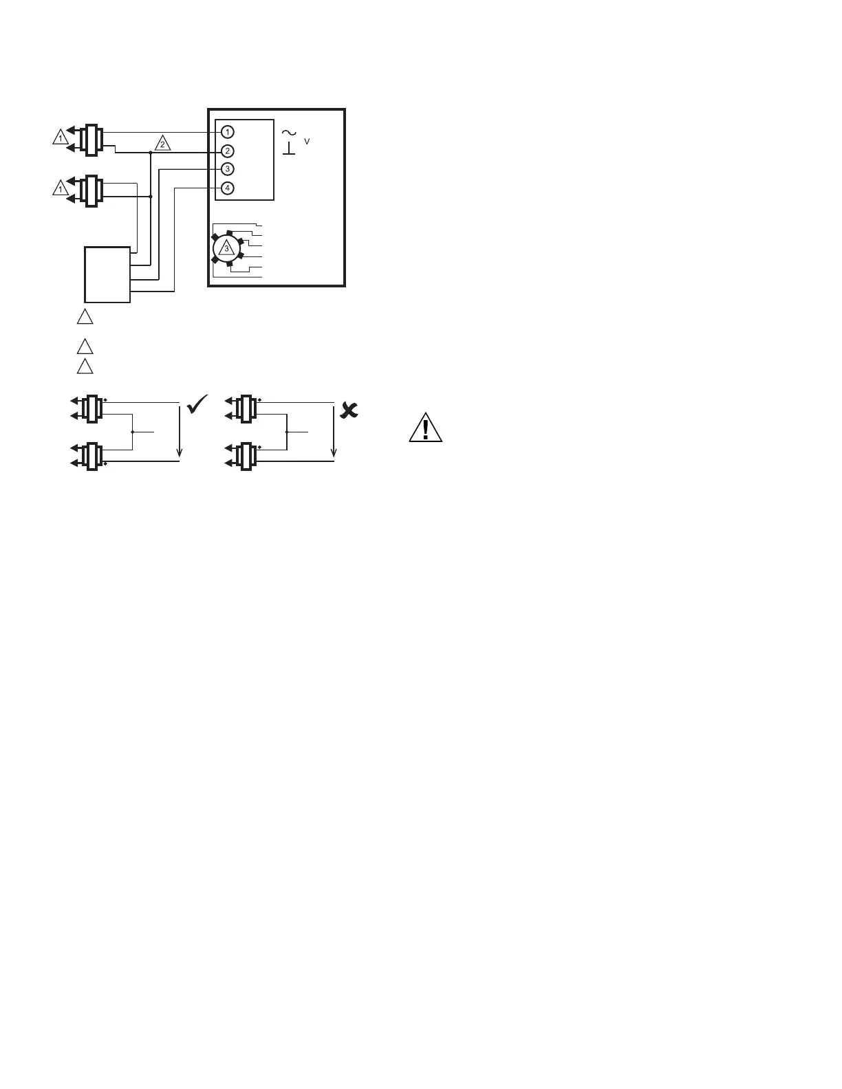
Fig. 18. Wiring for SYLK BUS control with separate
transformers, MS3103.
OPERATION
The actuator is designed to be used in ventilating and air
conditioning installations to operate valves, dampers,
ventilation flaps and louvers. (For ratings, see the
Specifications section.) If the power fails, the actuator will
spring return to the fail safe position.
When using a proportional controller and actuator is set to
(0)2 - 10 position, the actuator drives toward its fully open
position when the input signal increases; the actuator
drives toward the fully closed position when the input
signal decreases. The actuator stops when the input
signal reaches the desired proportional control point. This
operates in reverse when set to a 10-2(0) position.
IMPORTANT
The actuator is designed to respond to DDC
Controller instantaneous contact closures. Take
care not to short cycle the actuator. Unstable
damper control can cause premature actuator fail-
ure.
Fast commissioning mode
(modulating control mode and SYLK
communication only)
When 24 VAC or 24 VDC signal is applied to the
modulating input or on the SYLK communicating actuator
the position 6 (TEST) is selected, the actuator will drive to
the fully open position with higher speed corresponding to
30 sec timing. When the signal is disconnected, the
actuator will drive to the fully closed position with normal
operation timing.
Do not use fast test mode for permanent
operation.
Lifetime will be reduced if this mode is used
permanently. This mode is intended to be used only
for initial commissioning/testing of the system
after installation. Power consumption is not
specified in this mode.
Auxiliary Switches
Some models include Auxiliary switches. For wiring details
see Fig. 11.
Actuator Override
To override the control signal (for freeze protection or
similar applications):
1. Override to full open (fast commissioning, drive
mode lower than 30 sec):
a. Disconnect the input signal (from terminal 3).
b. Apply 24 VAC to terminal 3.
c. See Fig. 19.
NOTES: When using two transformers in the installation, make sure you connect
the corresponding legs of the secondary windings as Common. Check
voltage as shown in the picture and make sure it is lower than 30 VAC.
If not, swap the legs of one secondary winding.
1
2
3
LINE VOLTAGE POWER SUPPLY. PROVIDE DISCONNECT MEANS
AND OVERLOAD PROTECTION AS REQUIRED.
24 VDC SUPPLY ACCEPTABLE.
ADDRESS SELECTOR
24 VAC
CLASS 2
24 VAC
CLASS 2
24 VAC
CLASS 2
24 VAC
CLASS 2
24 VAC
CLASS 2
TO ACTUATOR HOT
TO CONTROLLER HOT
COMMON
< 30 VAC
TO ACTUATOR HOT
TO CONTROLLER HOT
COMMON
> 30 VAC
24 VAC
CLASS 2
S-BUS
S-BUS
RED
BLACK
BROWN
BROWN
ACTUATOR
ADDRESS 11
ADDRESS 12
ADDRESS 13
ADDRESS 14
ADDRESS 15
TEST
HOT
COM
CONTROLLER
S-BUS
S-BUS
 Loading...