2 HS-NCM Installation Document — P/N 54014:C1 12/15/2020
One HS-NCM can provide network communication for up to two nodes (including fire alarm control panels and network annunciators).
Per UL 864 10th Edition, the HS-NCM uses Active Multiplex Type 3 Communication.
The HS-NCM can also be configured as a high-speed repeater for applications requiring distances beyond the specified limits between two nodes. For
configuration and setup information, refer to “HS-NCM Configuration” on page 6. For limitations and network wiring information for the HS-NCM,
refer to the High-Speed Noti•Fire•Net Manual.
For instructions on the additional capabilities available with the DVC-EM, refer to the DVC and DAA Series Installation Manual.
Input power requirements: 17-28 VDC, 0.450 A, regulated, power-limited compatible power supply UL/ULC listed for fire protective signaling use
Communications circuit requirements: Refer to the High-Speed Noti•Fire•Net Manual for segment length limitations.
2 Network Communications Module for Wire (HS-NCM-W/W-2)
• Supports twisted-pair wire medium
• NFPA Class B operation or NFPA Class X operation
• Transformer coupling provides electrical DC isolation between nodes
• Pluggable terminal wiring with strain relief
• Pluggable service connector (feeds signal directly through) in the event that power must be removed from a node (HS-NBB)
• Data is regenerated at each node
• Two NUP ports to allow simultaneous connection of up to two fire alarm control panels and a programming computer
• Enables software and database upload/download over High-Speed Noti•Fire•Net
NOTE: All wiring connections are supervised and power limited.
Communication Circuit Voltage and Current Rating/Protocol
TB4 (Ch A - Wire Only) 10 VDC, 25mA
TB5 (Ch B - Wire Only) 10 VDC, 25mA
J6 (NUP) 232 Protocol
J7 (NUP) 232 Protocol
J8 (Ethernet Connection)
*
* Refer to Section 7, “Diagnostic Indicators” for details on the use of this connection
Standard Ethernet Physical Protocol
J13 (USBA) Standard Protocol
J14 (USBB) Standard Protocol
Table 1 Voltage and Current Ratings for Communication Circuits
NOTE: For use with the NFS-640, NFS2-640, NFS-320, NFS-3030, NFS2-3030, N16/E/N16/X, DVC-EM, NCA-2, NCA, and NCD the HS-
NCM must be connected via the NUP Ports!
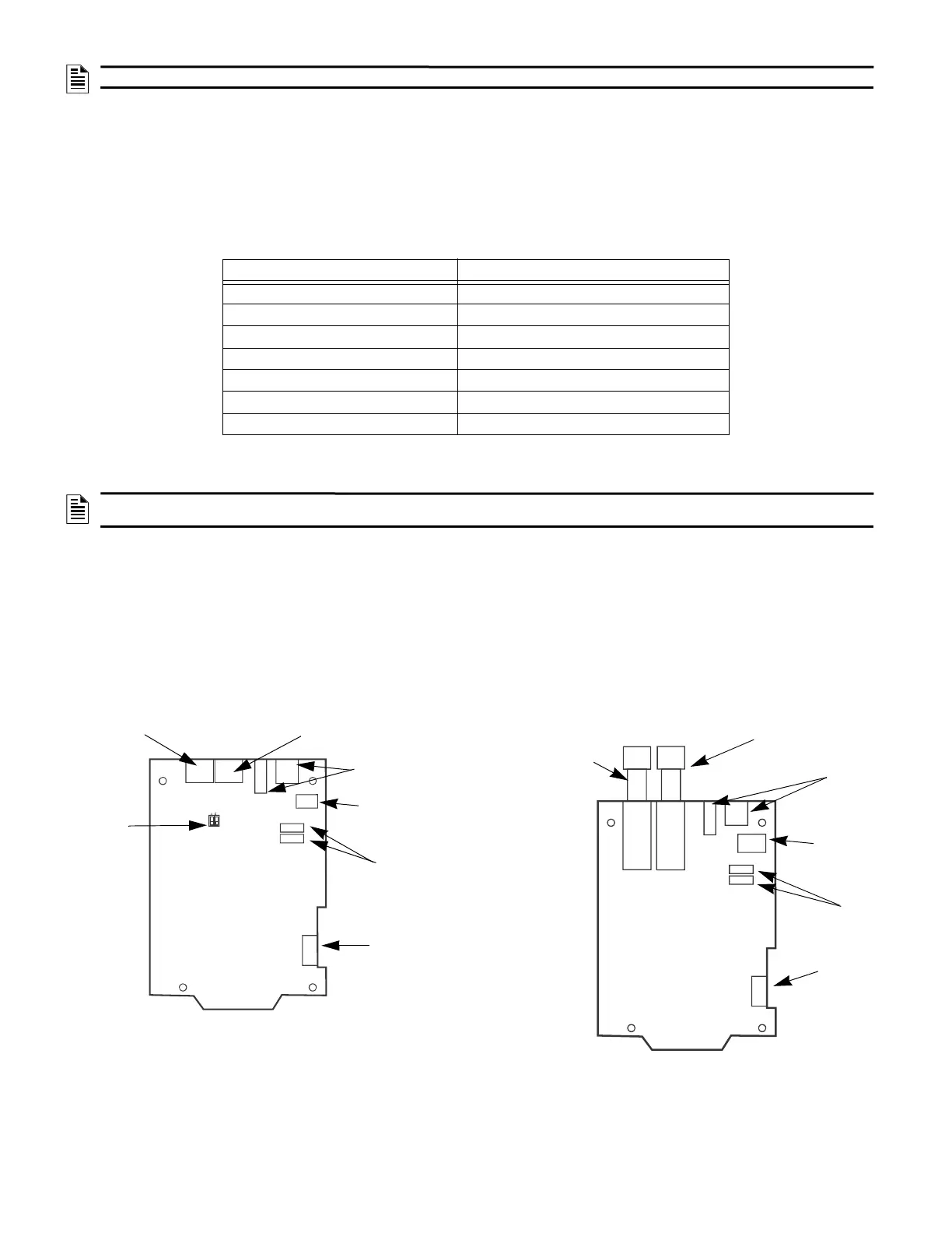
NUP
Ports
External
Power
Connection
USB
Connections
Channel B With SFP BroadR-
Reach Wire Module
Channel A
With SFP BroadR-Reach
Wire Module
Figure 2 HS-NCM-W-2
Ethernet
Connection
Ground Fault
Detection
Switches
S1=CH. A
S2=CH. B
Figure 1 HS-NCM-W
NUP
Ports
Channel B VDSL Wire
Connection
Channel A VDSL
Wire Connection
USB
Connections
External
Power
Connection
Ethernet
Connection
 Loading...


