18 NFN-GW-EM-3 Installation and Operation Manual — P/N LS10017-000NF-E:D1 5/1/2019
Installation Connections
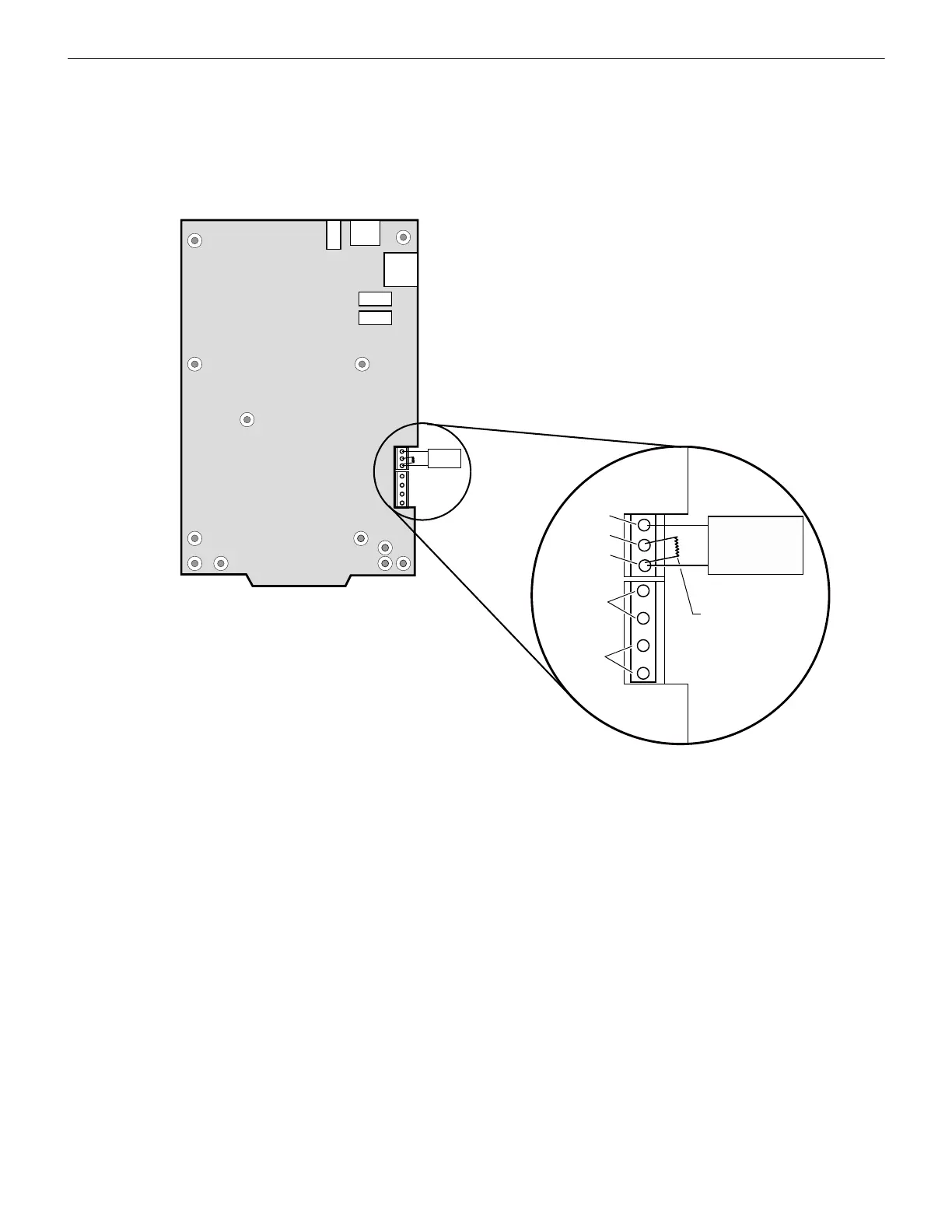
2.3.2 Trouble Relay Connections
The NFN-GW-EM-3 can be supervised by using an input module on an FACP. During normal operation (when the NFN-GW-EM-3 is
not detecting an error) it activates the internal relay. When the relay is active, the input module detects the end-of-line resistor. When
the NFN-GW-EM-3 detects an error, it deactivates the internal relay and posts an event to the error log (refer to 3.2.7, "Error Log").
This breaks the connection across the end-of-line resistor causing the input module to detect a trouble. This also occurs if the NFN-GW-
EM-3 does not have power.
Figure 2.7 TB-1 Trouble Relay
Supervised
Input
Module
TB1
N.O.
Com.
N.C.
TB2
–
Resistor value is
determined by the
supervising module.
24V Out
+
–
24V In
+

 Loading...


